
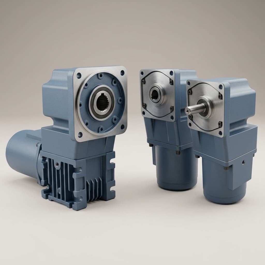
Cycloidal vs. Planetary Wheel Drives for Heavy AMRs and AGVs: Sourcing and Sizing Guide for 1–5 Ton Payloads
Compare cycloidal vs. planetary wheel drives for 1–5 ton AMRs and AGVs. Check wheel loads, sizing and supplier evidence, then prepare an engineering RFQ.
Cycloidal vs. planetary wheel drives for heavy AMRs and AGVs should be compared using per-wheel bearing loads, duty torque, speed and the complete installation envelope. A 1–5 metric ton payload is a starting requirement, not a gearbox rating. Both architectures can be suitable when the selected wheel, bearing, gearbox, motor and brake meet the same operating conditions.
This guide helps OEM engineers and procurement teams turn that requirement into a comparable RFQ. For a first torque and speed estimate, use the AMR drive gearbox sizing calculator; bearing life, braking and thermal approval require separate supplier evidence.
Executive sourcing takeaways
- Separate payload from gross vehicle mass, then calculate the maximum reaction at each wheel.
- Compare the actual bearing arrangement and wheel offset. An integrated hub can use either planetary or cycloidal reduction.
- Distinguish continuous, acceleration and emergency-stop ratings, including permitted duration and number of events.
- Choose between models that pass the load cases. Payload alone cannot establish a universal cost, life or reliability winner.
1. Scope, Date, and Decision Boundaries
Content date and last engineering review: October 27, 2026. This guide addresses global sourcing for indoor industrial AMRs and AGVs carrying 1,000–5,000 kg of payload. Gross vehicle mass includes the empty vehicle, battery, installed equipment and payload; it will exceed payload alone. Load support may be shared between driven wheels and casters.
RV Reducer publishes this guide from a supplier perspective. The worked example is a reproducible calculation using stated assumptions, not a measured product comparison, customer deployment or fleet reliability study. Catalog examples below illustrate design differences; they do not qualify an RV Reducer product or another supplier's model for your vehicle.
The scope includes differential and steerable traction drives. Mecanum motion, caster scrub, uneven suspension loading, towing, slopes and outdoor impacts need additional load cases. This guide excludes robot-arm joint sizing and does not establish machine safety compliance.
ISO 3691-4:2023 covers safety requirements and verification for driverless industrial trucks and their systems. Its public abstract establishes scope, not a gearbox shock factor or a mandatory stop category. Confirm the applicable edition and destination-market requirements during machine safety assessment.
2. The Core Mechanical Bottleneck: Cantilevered Overhung Radial Loads
A wheel attached to a gearbox output applies radial load, lateral load and bending moment to its support. The distance between the wheel load line and the effective bearing support matters as much as nominal torque. A short wheel offset can benefit either gearbox architecture.
Conceptual load-path diagram, not a product section drawing. The right-hand arrangement reduces radial-load leverage; lateral forces and other moments still require checking. Scroll horizontally on narrow screens. Both planetary and cycloidal drives can use compact wheel support.
A screening moment calculation
For a conservative sum of the radial-offset and lateral-force contributions, use:
M_screen = abs(F_r × e) + abs(F_a × r)
Here F_r is the radial wheel load in N, F_a the lateral wheel force in N, e the offset from the supplier's effective bearing reference in m, and r the loaded wheel radius in m. The result is N·m. This is a screening bound for those contributions, not a full bearing reaction or three-dimensional moment calculation. Steering geometry and traction forces can add other moments. A mounting-face dimension is not automatically the bearing lever arm.
Worked example — hypothetical inputs: 2,000 kg payload + 800 kg empty vehicle = 2,800 kg gross mass. Assume four equally loaded support wheels on a level floor, two of which are driven, with no load transfer. Each support wheel carries 2,800 × 9.81 / 4 = 6,867 N. With no lateral force, a 50 mm bearing offset produces 6,867 × 0.050 = 343.35 N·m; reducing it to 20 mm gives 137.34 N·m.
These numbers do not determine bearing life. Actual suspension, center of gravity, turning, braking and floor transitions can increase individual wheel reactions. Ask the supplier to calculate combined loading at the specified wheel center and mounting datum.
Check the bearing arrangement independently of gear type
AGV planetary gearboxes need not use lightly supported, long output shafts. The Neugart NGV product page describes preloaded angular-contact roller bearings and a gearbox almost enclosed by the wheel. It lists maximum dynamic support capacities of 350, 675 and 1,075 kg for its three gearbox-and-wheel combinations. Those catalog conditions cannot be treated as guaranteed life ratings or extrapolated directly to a complete vehicle.
Cycloidal units also differ. The Nabtesco RV component-set page states that its RV component sets do not integrate an angular-contact output bearing; the application designer selects the external support. Do not assume that every RV reducer includes a cross-roller bearing or is ready to carry a wheel directly.
3. Shock Load Tolerance: Floor Transitions and Emergency Stops
Specify the route's step height, joint width, approach speed, loaded wheel diameter and tire compliance. A floor gap width is not a vertical obstacle height. Tire, suspension and controller behavior determine impact loads; a fixed multiplier cannot be inferred from vehicle payload.
Planetary gears share torque through multiple planets. Cycloidal mechanisms distribute load through multiple disc-and-pin contacts. Neither load-sharing principle makes a drive immune to damage. RV-style reducers can also include a spur-gear input stage: Nabtesco's mechanism description explicitly shows two reduction stages, rather than a universally toothless single-stage transmission.
The same engineering page advertises emergency-stop capacity of five times rated torque for its technology. Treat this as manufacturer-specific information, not a repeatable operating rating for all cycloidal wheel drives. Request the exact model's permitted peak torque, speed, duration, event count and inspection requirements. Compare those limits with both controlled braking and fault-stop cases.
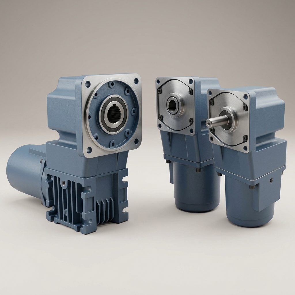
4. Architectural Comparison: Planetary vs. Cycloidal Wheel Drives
Use this matrix to request comparable evidence. The entries describe design questions, not universal performance ranges.
| Selection dimension | AGV-optimized planetary drive | Cycloidal / RV-style drive | Evidence needed before selection |
|---|---|---|---|
| Reduction mechanism | Sun, planets and ring; one or more stages | Disc-and-pin reduction; RV designs may include an input gear stage | Exact ratio and mechanism drawing |
| Wheel support | Can include reinforced bearings and an integrated wheel | Can include a main bearing, or require external support | Bearing layout and wheel-center load limits |
| Shock capacity | Model-specific peak and emergency ratings | High short-term ratings available on some models | Torque, duration and allowed event count |
| Ratio and speed | Check available ratios against motor operating range | High ratios may constrain wheel speed or backdriving | Input/output speed limits and motor curve |
| Efficiency and heat | Depends on stages, load, speed and lubrication | Depends on geometry, load, speed and lubrication | Efficiency map and duty-cycle thermal approval |
| Packaging | Inline, right-angle and wheel-integrated arrangements exist | Compact flange and hub arrangements exist | Complete motor/brake/wheel CAD and service clearance |
| Backlash and stiffness | Precision options vary by model | Low hysteresis designs available | Measurement definition, test torque and loaded stiffness |
| Service life | Bearings, gears, seals and lubricant have separate limits | The same component-specific limits apply | Load-spectrum life calculation and maintenance terms |
| Installed cost | Gearbox price alone omits support and integration | Higher component price may or may not reduce assembly cost | Matched-scope quote, validation, spares and lead time |
5. Wheel Torque, Speed, Ratio, and Chassis Space
Continue the 2,800 kg example with a loaded wheel radius of 0.125 m, two equally sharing drive wheels, level straight travel, rolling resistance coefficient 0.02 and acceleration of 0.5 m/s². These are illustrative assumptions, not measured floor or tire properties.
F_required = m × a + m × g × c_rr
T_wheel = F_required × r / N_drive
The total required traction force is 2,800 × 0.5 + 2,800 × 9.81 × 0.02 = 1,949.36 N, giving 121.84 N·m per driven wheel. This is output torque before allowances for rotating inertia, slope, turning, load imbalance and the selected service factor. The four support wheels determine vertical reactions; the two driven wheels share propulsion torque. Do not substitute one count for the other.
At 1.0 m/s, wheel speed is 60 × 1.0 / (2 × pi × 0.125) = 76.39 rpm. A motor operating at 3,000 rpm suggests a reduction ratio near 39.27:1. Select an available ratio and recheck both speed and motor torque over the duty cycle, including reducer losses and motor peak-duration limits. Also check available tire-floor traction using the normal load on the driven wheels; enough gearbox torque does not guarantee enough grip.
For packaging, compare the whole assembly: wheel, reducer, motor, brake, connectors, cable bends and tire-replacement access. A low chassis or narrow track does not by itself prescribe cycloidal reduction. Approve supplier CAD against the actual ground clearance and payload-lifting envelope.
To reproduce the level-floor torque and speed estimate, enter these assumptions in the AMR drive gearbox calculator. Its outputs do not approve bearing life, thermal duty or braking capacity.
6. Continuous Duty Thermal Management & Bearing Life
Request gearbox efficiency at the intended ratio, torque and speed. For steady operation, reducer heat loss can be estimated as P_loss = P_output × (1 / efficiency - 1). Tire hysteresis, motor losses and brake drag add other heat sources. A wheel enclosure can restrict heat rejection, so confirm the mounting heat path and test the installed assembly at the specified ambient temperature.
T_RMS = sqrt(sum(T_i² × t_i) / sum(t_i)) can help screen motor heating where torque tracks current. It does not replace the gearbox manufacturer's thermal method, which must also consider speed-dependent losses, lubrication and cooling. There is no universal 65%-of-rated-torque rule that guarantees 20,000 hours. Use supplier-approved lubricant, seals, temperature limits and maintenance intervals.
For bearings at constant speed, the SKF bearing-life method uses L10h = 1,000,000 / (60 × n) × (C / P)^p, with speed n in rpm, dynamic rating C and equivalent bearing load P in matching units, and exponent p = 3 for ball bearings or 10/3 for roller bearings. L10 describes 90% population survival under the stated conditions, not a warranty for an individual assembly.
The equivalent load requires the actual bearing arrangement and combined load reactions. Do not substitute a wheel's radial reaction directly for P when offset moments, axial loads or preload matter. Variable-speed duty, contamination, lubrication and static indentation checks need separate treatment. A 20,000-hour project target is a requirement to validate, not an inherent property of either reducer architecture.
7. Potential Failure Modes and Verification Requests
These are engineering risks to investigate, not measured comparative failure rates.
| Potential failure mode | Relevant load or condition | Request from either supplier |
|---|---|---|
| Bearing fatigue or indentation | Combined wheel reaction, offset moment and impact | Life calculation plus static-load check at the actual wheel center |
| Gear, pin or input-stage damage | Braking, floor impacts or repeated overload | Model-specific peak limits and approved event counts |
| Seal leakage | Deflection, contamination and thermal cycling | Assembled-unit sealing specification and test conditions |
| Docking error after reversals | Backlash, elastic deflection, tire slip and control tuning | Loaded reversal and docking acceptance test |
| Motor interface fretting | Misalignment, poor fit or loose connection | Interface tolerances, fastener method and assembly inspection |
| Tire bond degradation | Load, tread heating and hub heat transfer | Wheel supplier's load/speed/temperature envelope and replacement procedure |
8. Sourcing Decision Matrix: When to Shortlist Each Architecture
Shortlist an AGV planetary unit when its wheel support passes the combined loads, its ratios suit the motor and travel speed, and its complete assembly meets the packaging and duty requirements. A wheel-integrated planetary design is a valid candidate for a heavy vehicle if the exact configuration passes those checks.
Shortlist an integrated cycloidal unit when a candidate offers useful moment capacity, stiffness, peak-load capability or packaging for your application. Confirm that output bearings are included, that the available ratio permits travel speed, and that losses and recovery behavior are acceptable. A robot-joint reducer is not automatically a qualified traction drive.
Reject either candidate if the supplier cannot document wheel loads, stops, thermal duty or maintenance at your conditions. Consider external wheel bearings or a different support layout when torque capacity passes but bearing support does not.
After technical screening, compare total installed cost using the same quantity, destination, delivery terms, wheel, motor, brake, adapter, external support, validation work and spare-parts scope. Obtain current quotations; no universal 25–40% price saving or tonnage-based TCO crossover is supported here.
9. Sourcing & RFQ Engineering Checklist for Procurement Teams
Send both suppliers the same application sheet:
- Mass and wheel reactions: Payload, empty vehicle mass, center of gravity, driven/support wheel counts, suspension arrangement and maximum load at each wheel.
- Geometry: Loaded wheel diameter, tread width, wheel-center offset, bearing reference datum and mounting drawing revision.
- Motion and route: Speed, acceleration, ramps, turning radius, step heights, joint widths, floor condition and tire properties.
- Duty spectrum: Torque and speed by operating segment, travel/dwell time, shift length and ambient/enclosure conditions.
- Peak events and braking: Stop profiles, events per hour and over life, brake location, parking-on-slope requirement and permitted towing/recovery procedure.
- Life evidence: Agreed operating-hour target, bearing calculation assumptions, static-load check, component exclusions and warranty conditions. Separate design life from warranty.
- Sealing and lubrication: Required ingress tests for the assembled drive, actual cleaning exposure, lubricant specification and maintenance interval. An IP label alone does not approve a cleaning process.
- Motor and brake interface: Exact motor curve, feedback, voltage, brake function, adapters, fasteners and responsibility for integration.
- Precision acceptance: Backlash or hysteresis definition, test torque, stiffness, inspection method and loaded docking criteria; avoid an undefined “zero backlash” promise.
- Commercial and validation scope: Quantity breaks, delivery destination, quote validity, lead time, spares, drawing control, prototype tests and records required before production approval.
10. Frequently Asked Questions (FAQ)
Can a planetary wheel drive handle a 5-ton AGV payload?
Potentially, with a suitable model and load-support arrangement. Calculate gross vehicle mass and the worst wheel reaction first; do not divide payload alone by the number of driven wheels. Wheel capacity, bearing moments, speed, duty torque and braking all need approval. A catalog support-load figure is insufficient to qualify a complete 5-ton vehicle.
Are cycloidal reducers always single-stage and equipped with cross-roller bearings?
No. The cited Nabtesco mechanism uses an input spur-gear stage followed by cycloidal reduction, and its RV component sets leave output bearing selection to the integrator. Confirm the exact product's mechanism and included bearing arrangement before using a generic RV label in an RFQ.
Can an unpowered AGV with a cycloidal drive be pushed or towed?
Do not assume manual recovery is possible from gear type alone. Ratio, internal friction, motor/controller behavior and the brake-release mechanism matter. Ask the vehicle integrator for the approved towing speed, distance, release procedure and electrical isolation requirements, including how the vehicle is restrained during brake release.
What tire material is best for a heavy wheel hub drive?
Choose using load per wheel, speed, temperature, floor traction, chemical exposure and allowable floor pressure. Hardness alone does not establish suitability. Have the wheel supplier confirm rolling resistance, bond temperature limits and loaded radius for the actual mission, then include those values in sizing and thermal tests.
Does lower backlash guarantee millimeter-accurate docking?
No. At a 125 mm wheel radius, an 8 arcmin angular gap corresponds to about 0.291 mm of geometric rim travel: s_mm = radius_m × backlash_arcmin × pi / 10,800 × 1,000. This is not the complete vehicle position error. Tire slip, compliance, encoder location, control behavior and localization also affect docking; verify the loaded vehicle in reversal and docking tests.
Does ISO 3691-4 certify the gearbox?
The cited standard addresses driverless industrial trucks and their systems. A reducer catalog claim does not demonstrate vehicle compliance. The integrator must assess the complete machine and applicable requirements; this article does not prescribe a universal emergency-stop category or certify any drive.
11. Next Steps: Turn the Calculation into a Comparable RFQ
Select the support layout and calculate loads before choosing a reducer family. Use supplier evidence to eliminate unsuitable models, then compare the installed cost and maintenance terms of those that remain.
- Review torque and service-factor concepts: Our heavy-payload RV reducer selection guide addresses articulated robot joints. Its general torque discussion is useful context, but its joint load cases must not replace wheel-drive sizing.
- Plan monitoring after qualification: The RV reducer condition monitoring guide introduces monitoring topics; establish baselines on your selected drive and mission.
- Request a drawing-specific review: Contact the RV Reducer technical team with gross mass, maximum wheel reaction, offset, speed, stop profile, duty cycle and quantity. Request a model-specific load calculation, CAD envelope and matched-scope quotation before freezing the chassis design.
Sources / References
Sources checked on October 27, 2026. Manufacturer statements apply to the identified products and conditions; they are not independent comparative tests or transferable RV Reducer ratings.
- ISO — ISO 3691-4:2023: Official standard record and public scope. Supports the machine/system scope only; no clause-specific gearbox multiplier is asserted.
- Neugart — NGV: Application-specific planetary gearbox and wheel data. Supports the integrated planetary packaging, bearing concept and model-specific support-load examples.
- SKF — Bearings and Mounted Products, “Bearing life”: Official catalog PDF, printed page 18 (PDF page 20). Supports the basic rating-life equation and statistical/operating-condition limitations.
- Nabtesco Motion Control — Engineering: Cycloidal mechanism and performance overview. Supports the two-stage RV mechanism and the manufacturer's stated short-term emergency-stop capacity.
- Nabtesco — RV: RV component-set product description. Supports the distinction between a reducer component set and an assembly with integrated output bearings.
Author

Categories
More Posts
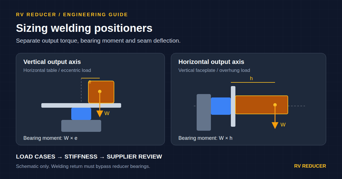
Robotic Welding Positioners and Turntables: Sizing RV Reducers for Overturning Moment, Tilting Stiffness, and Electrical Arcing Protection
Size RV reducers for welding positioners: compare torque, overturning moment, tilting stiffness and welding return paths. Prepare a complete engineering RFQ.
Predictive Maintenance for RV Reducers: A Buyer's and Engineer's Guide to Condition Monitoring
Discover how vibration analysis and thermal imaging can detect RV reducer degradation hours before failure, reducing TCO and unplanned downtime.
Hollow Shaft RV Reducers: Engineering and Sourcing Guide for Internal Cable Routing
Discover how hollow shaft RV reducers solve high-density wiring challenges in modern robotics. A complete guide on torque ratings, bore sizing, and procurement.