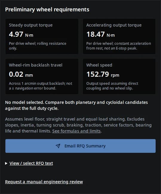
The default example needs 4.97 N·m steady and 18.47 N·m accelerating torque per driven wheel at 152.79 rpm. These are calculated demands, not catalog approvals.
The source table includes precision options from both planetary and cycloidal series. Match speed, ratio and measurement conditions before comparing their headline numbers.
Wheel reactions and offset determine the bearing load case. Request a model-specific calculation; an integrated bearing does not imply approval for a given robot mass.
The tool uses a level-floor force balance and an arc-length conversion. Define m as empty mass + payload (kg), r as wheel diameter / 2000 (m), N as driven wheels, v as speed (m/s), t as acceleration time (s), c as rolling resistance coefficient and b as output backlash (arcmin). Use g = 9.81 m/s².
On small screens, scroll horizontally. Keyboard: focus the table region and use arrow keys.
Reproducible calculator equations
Output
Equation
Interpretation / exclusion
Steady torque per wheel (N·m)
Tsteady = m × g × c × r / N
Straight travel on a level floor, equally shared. No slope or caster scrub.
Accelerating torque per wheel (N·m)
Taccel = [m × g × c + m × (v / t)] × r / N
Constant acceleration from rest. Excludes rotational inertia, jerk and braking.
Wheel speed (rpm)
n = 60 × v / (2 × π × r)
Direct wheel coupling; no slip or tire deformation.
Wheel-rim backlash travel (mm)
s = b × π / 10800 × r × 1000
Arc length across the entered angular gap; not a ± position bound.
Gearbox efficiency is not applied to wheel/output demand. Motor torque would require a chosen reduction ratio i and operating-point efficiency η: Tmotor = Toutput / (i × η). A motor and ratio are not selected here. No service factor is added; final margin must follow the supplier’s duty-rating method.
Three reproducible sizing scenarios
Illustrative calculations, not field tests. All use 150 kg empty mass + 300 kg payload, two driven wheels, 1.2 m/s, c = 0.03 and 1 arcmin backlash. Baseline diameter is 150 mm and acceleration time is 1.5 s; each alternative changes only the stated input.
On small screens, scroll horizontally. Keyboard: focus the table region and use arrow keys.
Calculated level-floor scenarios — torque is per driven wheel
Scenario
Steady / accelerating (N·m)
Wheel speed (rpm)
Rim travel (mm)
Next decision
Default level-floor robot
4.97 / 18.47
152.79
0.0218
Check the candidate at the calculated wheel speed and repeated acceleration duty.
Faster launch: 0.5 s to speed
4.97 / 45.47
152.79
0.0218
Acceleration demand rises; validate motor current, traction and repeated peak duration.
Larger wheel: 300 mm diameter
9.93 / 36.93
76.39
0.0436
Torque and backlash travel double while wheel rpm halves; recheck ratio and wheel offset.
Try these inputs in the calculatorActual calculator run captured 27 September 2026 with the default inputs above; result panel only. This demonstrates the software output, not measured gearbox performance or a customer result. Small backlash travel is rounded to 0.02 mm in the tool; the scenario table retains four decimal places.
Backlash travel is not navigation accuracy
Original geometric diagram; no scale or measured performance is implied.
Example: 10 arcmin on a 150 mm radius gives 0.4363 mm across the angular gap. A 150 mm diameter gives half that distance. The tool always asks for diameter.
A motor-side encoder may not observe downstream free play. Output sensing, wheel slip, tire compression, compliance and localization all change the vehicle-level outcome. Measure repeatable docking performance under the intended load.
Do not sum this number over a route or use it to set LiDAR update frequency. Also confirm whether a catalog reports backlash, lost motion or loaded hysteresis before entering its value.
Compare specific gearbox evidence
Public examples reviewed 27 September 2026. These series illustrate the questions to ask; they are not equivalent-size test results, available offers or recommendations for the default robot. Neugart marks PSN as discontinued and directs new projects to PSNpro; the historical PSN figures below do not describe the replacement series.
On small screens, scroll horizontally. Keyboard: focus the table region and use arrow keys.
PSN source: reduced backlash below 1 arcmin for sizes 090–190.
Different definitions. Request measurement torque and configuration before ranking precision.
Efficiency
Series page states up to 85%.
Technical data lists 97–98%.
Not a matched operating-point comparison; obtain efficiency at your actual torque, speed and temperature.
Shock and repeated peaks
Series advertises shock resistance up to 5× nominal torque.
Check the exact model’s peak and emergency-stop ratings.
An occasional shock allowance cannot be used as a repeated acceleration or safety rating.
Wheel support
Integrated main bearing; capacity is configuration dependent.
Shaft/bearing loads require the selected configuration.
No robot payload capacity established here. Check radial/axial loads, overhang and moment.
Purchase and integration cost
Current price, availability and AMR-specific integration cost: unknown.
PSN is discontinued; obtain a current replacement-series quote and validate its specifications.
Quote gearbox, support bearings, adapters, validation and spares together.
Where this estimate needs a different model
On small screens, scroll horizontally. Keyboard: focus the table region and use arrow keys.
Misuse, cost and scenario risks with next actions
Trigger
Risk
Minimum next action / alternative
Ramp, curb, uneven floor or skid-steer turn
Level-floor torque underestimates grade, shock or scrub loads.
Measure the route load cases; include slope, traction and turning before sizing.
Directly supported wheel with overhang
Output bearing moment can govern even when torque is small.
Supply wheel-center offset and load distribution; consider an external bearing if capacity is insufficient.
Frequent reversing or emergency stops
Acceleration estimate omits stopping profiles and repeated shock limits.
Provide braking deceleration, inertia and cycle counts; validate truck-level safety separately.
Long continuous shifts or sealed wheel hub
Unverified thermal duty or lubrication life can limit operation.
Request continuous torque at speed, ambient limit and a representative thermal test.
Choosing the lowest gearbox unit price
Adapters, external bearings, control tuning and downtime may dominate installed cost.
Compare complete assemblies and replacement access; obtain current quotes instead of assuming a family is cheaper.
ISO 3691-4:2023 addresses safety requirements and verification for driverless industrial trucks and systems. This calculator does not evaluate compliance. Confirm the applicable edition when the design is assessed.
Turn the results into a reviewable specification
On small screens, scroll horizontally. Keyboard: focus the table region and use arrow keys.
Known outputs and missing engineering evidence
Item
Known here
Still required before selection
Torque and speed
Calculated steady/accelerating demand and wheel rpm.
Load spectrum, ratio, motor curve, duty torque and speed ratings.
Precision
Geometric wheel-rim travel from an entered angular gap.
Measurement definition, torsional deflection and loaded docking tests.
Bearing life
Unknown: no bearing geometry or wheel reaction inputs.
Radial/axial load, overhang, speed and supplier life calculation. SKF explains why life is load-dependent.
Thermal and braking capacity
Unknown: not computed.
Ambient, enclosure cooling, stops per hour and manufacturer approval of the duty profile.
Availability and installed cost
Unknown: no current quote.
Quantity, delivery location, motor adapter, support arrangement, spare units and written quotation.
SKF’s bearing-life guidance treats L10 as statistical life at stated load and speed. Do not infer a guaranteed 20,000-hour life or a vehicle payload rating from the presence of an integrated bearing.
AMR drive gearbox questions
Using the calculator
What do the torque results mean?
They are wheel/output torque demands for level, straight travel under the entered assumptions. Steady torque covers rolling resistance; accelerating torque adds constant acceleration from rest. Neither is a continuous gearbox rating or an emergency-stop rating.
Is the rolling resistance default a measured value?
No. The 0.03 default is an illustrative dimensionless assumption. Measure resistance using the actual loaded tires, floor and operating conditions. Changing it scales the steady torque contribution.
Can I use the result for slopes or skid steering?
No. Grade force, turning scrub, traction and wheel load transfer are excluded. Send route slope, drive layout and measured duty loads for an expanded calculation before selecting hardware.
Why does changing an input remove the results?
The RFQ must use the same inputs as the displayed calculation. Recalculate after any edit. Reset restores the illustrative inputs and clears the previous result.
Precision and gearbox choice
Is wheel-rim backlash travel my AMR positioning accuracy?
No. It is the geometric arc length across the specified output backlash: wheel radius × backlash in radians. Encoder location, slip, tire deformation, compliance and localization also affect vehicle position. It is neither a ± error bound nor cumulative route drift.
Are backlash and hysteresis interchangeable?
No. Catalog definitions and measurement torque matter. Loaded hysteresis can include elastic deformation; a free-play backlash value cannot be compared directly without checking the test method.
Is cycloidal always more precise than planetary?
No. The referenced PSN data lists reduced-backlash options below 1 arcmin for some sizes. Compare the exact configuration and measurement definition, then check output speed, duty torque and bearing support.
How do I choose the reduction ratio?
Divide the available motor speed by required wheel speed for a first candidate ratio. Then check motor torque-speed limits, gearbox input/output speed limits and available ratios. This tool does not select a motor or ratio.
Validation and purchasing
Does a 1.2× service factor make the design safe?
There is no universal factor established by this calculation. Evaluate the complete load spectrum and the supplier rating method, including braking, shock duration, repetition, inertia and thermal duty.
Can an integrated gearbox support a 1,000 kg robot?
Payload alone is insufficient. Check the load on each supported wheel, overhang, axial force, tipping moment, speed and required life against the actual bearing arrangement. Add external wheel support if the integrated bearing cannot meet those conditions.
Is 20,000 hours a guaranteed lifetime?
No. Bearing life is a statistical calculation for specified load and speed, and differs from gearbox or lubricant service life. SKF defines L10 at 90% survival for a population under the stated conditions; it is not a guarantee for an individual drive.
What should I send with the RFQ?
Include the generated brief plus route slope, wheel offset and load distribution, duty cycle, braking profile, motor curve and flange, ambient conditions, quantity and destination. Prices and lead times require a current quote; this page has no verified offers.
Sources and evidence limits
Reviewed 27 September 2026. Manufacturer statements below describe their named products, not RV Reducer inventory or an independent comparison. Calculated examples follow the disclosed equations; no field-test dataset is claimed.
Public scope and edition status only. The 2020 edition is withdrawn; ISO lists a revision in development. No clause-level certification assessment is made here.