
1. Separate operating and stopping loads
A running torque estimate does not establish emergency-stop capacity. Nabtesco publishes distinct rating categories; request their conditions for your selected model.
Estimate torque and ratio, then prepare a manufacturer RFQ. Start with the editable example below; use the evidence guide to check candidate gearboxes.
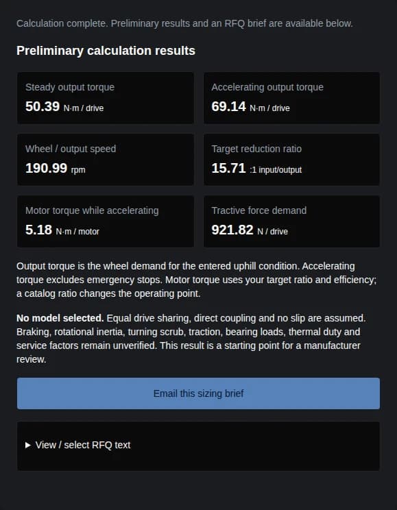
Calculate the example or enter your own values. You will get wheel torque, speed, a target ratio and the missing checks to discuss with a manufacturer.
Missing data? Request manual sizingPublished · Reviewed . Published by RV Reducer — Magatom Dynamics Co., Ltd.. Method and sources are reviewed every six months, or when the referenced specifications change.
Sources checked . This is a preliminary engineering guide; no specific model is approved by the calculator.
A running torque estimate does not establish emergency-stop capacity. Nabtesco publishes distinct rating categories; request their conditions for your selected model.
Integrated wheel support is available in planetary designs too. Neugart’s NGV is an example; verify bearings, wheel offset and mounting together.
Our sourcing recommendation: compare documented speed, torque and wheel loads. Public product examples support evaluating both architectures; they do not establish a universal 500 kg technology boundary.
The tool uses a straight-line uphill force balance, equal drive sharing and direct gearbox-to-wheel coupling. M is total moving mass, N is driven-wheel count, r is loaded wheel radius in metres, θ is slope in degrees, and g = 9.81 m/s². Trigonometry converts θ to radians internally.
| Output | Equation | Interpretation |
|---|---|---|
| Steady force (N) | F = M × g × (Crr × cos θ + sin θ) | Rolling resistance plus uphill gravity at constant speed. |
| Steady output torque (N·m / drive) | Tsteady = F × r / N | Demand at this operating point; not a validated continuous catalog rating. |
| Accelerating output torque (N·m / drive) | Taccel = (F + M × a) × r / N | Translational acceleration only; no emergency-stop or rotational-inertia allowance. |
| Wheel speed and target ratio | nwheel = 60 × v / (2πr); i = nmotor / nwheel | rpm and dimensionless input/output ratio; actual catalog ratios must be checked. |
| Accelerating motor torque (N·m / motor) | Tmotor = Taccel / (i × η) | η is gearbox efficiency at the operating point; drive electronics and motor losses are excluded. |
Defaults Crr = 0.05 and η = 0.85 are scenario assumptions, not measured AMR data. Confirm floor resistance and gearbox efficiency for your operating point. No blanket service factor is applied.
Illustrative calculations, not field tests. All three use M = 1,000 kg, two driven wheels, 150 mm wheel diameter, 1.5 m/s, a = 0.5 m/s², Crr = 0.05, η = 0.85 and motor speed 3,000 rpm. Only slope changes.
| Scenario / slope | Steady output (N·m) | Accelerating output (N·m) | Decision / next check |
|---|---|---|---|
| Level transit / 0° | 18.39 | 37.14 | Even on a level floor, acceleration changes the torque demand. Confirm the acceleration time and frequency. |
| Example ramp / 5° | 50.39 | 69.14 | Uphill gravity materially raises demand. Check traction and thermal duty on the ramp. |
| Steeper ramp / 10° | 82.00 | 100.75 | Use this as a supplier review case, not evidence that the vehicle can climb the slope. |
In-wheel / compact drive architecture: output support may carry wheel loads only when selected-model ratings match the AGV duty cycle.
Diagram reading: motor → reducer → wheel transmits torque; the wheel bearing and chassis carry support loads. This schematic shows one cycloidal arrangement. The calculator divides tractive effort among drives; it does not divide vehicle weight into bearing reactions. Obtain wheel offsets, centre-of-gravity position and suspension geometry for that separate calculation.
| Source | What is publicly supported | What remains unconfirmed |
|---|---|---|
| Nabtesco RV-E — product and specification table | The family lists an internal main bearing and separates rated torque, acceleration/deceleration torque and momentary allowable torque in its specifications. | Exact model, ratio, speed, duration, life and installation conditions for your AMR. A rating category is not a universal shock multiplier. |
| Neugart NGV — gearbox and wheel technical data | A planetary design with integrated wheel support. The NGV110 gearbox-and-wheel table lists maximum dynamic load capacity of 1,075 kg. | That figure describes the catalog assembly and its conditions, not total robot payload or another model’s capacity. Verify wheel, life and speed limits. |
| ISO 18646-1:2016 — public scope | The published scope covers specifying and evaluating indoor wheeled-robot locomotion performance. | The public scope does not substantiate a 500% gearbox shock-load rule. This page makes no certification or safety-compliance claim. |
The sources describe individual products and a standard’s scope. Matching efficiency curves, current pricing, sample availability and lead times for a proposed RV Reducer assembly remain unverified; request them with your RFQ. Public pages can change, so confirm the drawing and datasheet revision used in an offer.
| Decision | Cycloidal candidate | Planetary candidate | Ask the manufacturer for |
|---|---|---|---|
| Wheel support | RV-E demonstrates internal bearing integration; wheel suitability still needs confirmation. | NGV demonstrates an integrated wheel-bearing concept. | Combined radial/axial/moment limits at your offset, speed and target life. |
| Speed and ratio | Check the selected ratio and allowable output speed. | Check the selected stage count, ratio and speed. | A marked operating point and allowable duty-cycle envelope. |
| Shock and stop duty | Obtain model-specific start/stop and momentary ratings. | Obtain model-specific start/stop and momentary ratings. | Permitted torque, duration, frequency and braking assumptions. |
| Efficiency and energy | Comparable operating-point data not established here. | Comparable operating-point data not established here. | Efficiency map over your load/speed cycle; include auxiliary loads in battery estimates. |
| Packaging and total cost | Price the complete supported wheel module. | Price the complete supported wheel module. | CAD, motor adapter, wheel, seals, assembly, sample testing and maintenance costs. |
Stopping, parking on slopes, curb impacts, rotational inertia, traction and thermal life are outside the model. Submit load histories and measured prototype data for a separate review before design release.
Adapters, external bearings, wheel hubs and validation can change the module cost. Compare a complete bill of materials and sample-test plan; consider an integrated wheel module when support parts dominate.
Mecanum rollers, skid steering, uneven floors and unequal drive loading require a different force model. Use measured turning loads or a vehicle dynamics model; review traction at each driven wheel.
Use the calculator brief to start a discussion with RV Reducer. The items below are documents to request and agree, not claims that a specific factory, certificate or configuration has already been verified.
| You provide | Manufacturer should return | Acceptance checkpoint |
|---|---|---|
| Calculated brief plus velocity / torque time history | Model, ratio, rating conditions and sizing rationale | Running, accelerating and stopping cases checked separately. |
| Motor drawing, wheel diameter/offset, CAD envelope | Dimensioned assembly and interface drawings | Wheel loads, clearances, fasteners and service access reviewed. |
| Target life, temperature, floor and ingress conditions | Thermal/life assumptions, sealing and lubrication instructions | Agree a representative loaded test cycle and measured acceptance limits. |
| Backlash, inspection and traceability requirements | Sample inspection report, test method and lot identification | Confirm records apply to the offered model and revision. |
| Quantity, destination, project dates and spares needs | Written quote, sample plan, warranty and lead time | Verify scope, exclusions and total installed cost before ordering. |
Enter the total mass being moved: chassis, battery, payload and any towed mass. Driven wheels share the total tractive demand; passive casters are not counted as drives. This division does not estimate the vertical load on a particular wheel.
No. It covers forward acceleration against rolling and uphill resistance. Braking needs a separate time-history calculation including deceleration, slope direction, inertias, control behavior and stop frequency. Ask for the selected model’s allowable stop torque and duration.
There is no universal payload cut-off. Compare the actual ratio, speed, duty cycle, wheel loads and available envelope for each candidate. The NGV planetary example in the evidence table demonstrates why architecture alone cannot decide suitability.
The required force at the floor sets wheel torque. Gearbox losses increase the motor input torque needed to deliver it: motor torque = output torque ÷ (ratio × efficiency). Wheel and floor rolling losses are represented separately by Crr.
The requested wheel speed exceeds the entered motor speed, so that combination needs a speed increase. Review available motor speed or wheel diameter before seeking a reduction gearbox. The tool flags this state and includes it in the RFQ brief.
Only as a straight-line preliminary reference. Lateral roller losses, turning scrub and unequal load sharing are omitted. Send steering geometry and measured turning loads for a separate model before selecting hardware.
Request model-specific load ratings, dimensioned CAD, a motor interface drawing, traceable inspection records and a written test plan under your duty cycle. Agree sample acceptance, warranty terms and lead time before a purchase order.
Yes. Use “Request manual sizing” and identify missing values. For a calculated result, “Email this sizing brief” includes the inputs, estimates and exclusions. The selectable text is a fallback if an email application is unavailable.
Send the calculated brief, motor specifications, wheel offset and duty cycle. Ask for a proposed model, drawings, documented limits and a written quote. Availability and response timing require confirmation.
Inquiry Email
Include target torque/speed, quantity, and delivery location.