
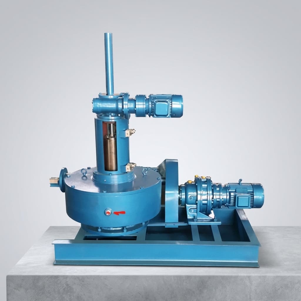
How to Select an RV Reducer for Heavy Payload Industrial Robots
A step-by-step engineering guide on sizing and selecting the correct RV cycloidal reducer for heavy payload industrial robotic arms and positioners.
Designing a heavy payload industrial robot (50kg to 1000kg+ capacity) is an exercise in managing extreme mechanical forces. At the core of every major joint—especially the base (Axis 1), shoulder (Axis 2), and elbow (Axis 3)—lies the RV (Rotary Vector) Reducer.
[!TIP] Key Takeaways
- Always calculate both static Gravity Torque and dynamic Acceleration Torque.
- Factor in the Safety Factor (Service Factor) based on your robot's duty cycle.
- For multi-axis setups, verify the Torsional Rigidity to ensure precision settling times.
Here is a practical engineering guide on how to size your RV reducer properly.
Step 1: Calculate the Maximum Output Torque
The first step is determining the maximum continuous and peak torques the joint will experience. This is not just about the payload weight; it involves the distance from the joint to the payload's center of gravity.
Basic Gravity Torque Formula:
T_g = W × L × g
T_g: Gravity Torque (N·m)W: Payload Mass (kg)L: Distance from joint center to payload center of gravity (m)g: Acceleration due to gravity (9.81 m/s²)
- Gravity Torque: Calculate the torque generated when the robot arm is fully extended horizontally.
- Acceleration Torque: Determine the torque required to accelerate the arm and payload to maximum speed within your required cycle time.
Ensure the reducer's Rated Torque exceeds your continuous gravity and acceleration requirements with an application-specific service factor. Avoid running close to catalog limits without supplier review, because bearing life, thermal rise, and lubrication margin can collapse quickly.
Step 2: Verify Emergency Stop (E-Stop) Torque
In industrial environments, safety scanners or power failures trigger emergency stops. When an E-stop occurs, the robot's servo motor brakes instantly, transferring the immense kinetic energy of the moving arm directly into the reducer.
Most RV reducer catalogs specify a Momentary Maximum Allowable Torque or short-duration peak torque. You must calculate your system's kinetic energy during a worst-case E-stop (arm fully extended at maximum speed) and check the resulting torque spike against the selected frame, ratio, bearing support, and supplier validation limits.
Step 3: Evaluate Moment Load Capacity
Heavy payload robots generate massive bending moments on the joints. The RV reducer does not just transmit rotational torque; its internal main bearings must physically support the structural weight of the robot arm.
- Review the Main Bearing Moment Load ratings. Many robot-grade RV reducers use integrated angular contact ball bearings or cross roller bearings to handle radial, axial, and overturning loads together.
- If your bending moment exceeds the reducer's capacity, you will need to design an external bearing support structure, which increases weight and complexity.
Step 4: Check Torsional Rigidity and Resonance
When a heavy robot arm stops, you want it to settle immediately. If the joint lacks rigidity, the arm will vibrate for several seconds, ruining your cycle time and path accuracy.
- Check the reducer's Torsional Rigidity (measured in N·m/arcmin). Higher rigidity means less deflection under load.
- Ensure the natural frequency of the mechanical system (motor + reducer + arm + payload) does not align with the servo motor's driving frequency, which could cause destructive resonance.
Step 5: Input Speed and Thermal Limitations
Heavy-duty reducers are densely packed metal structures. Pushing them to high input speeds generates significant friction and heat.
- Verify the Allowable Maximum Input Speed. If you are using a 3000 RPM servo motor, ensure the reducer is rated for it.
- Consider the duty cycle. If the joint is moving continuously, thermal buildup will thin the grease, increasing wear. If your application has a continuous duty cycle over 50%, you may need to upsize the reducer or implement active cooling.
Summary
Selecting the right RV reducer requires a careful balance of torque, rigidity, and thermal management. A robust selection process helps your robotic platform hold its backlash, stiffness, and life targets through real duty cycles.
If you are developing a new robotic platform or struggling with joint rigidity on an existing design, contact our engineering team. Share your duty cycle and payload data so we can review candidate frames, ratios, and validation risks for your application.
More Posts
Predictive Maintenance for RV Reducers: A Buyer's and Engineer's Guide to Condition Monitoring
Discover how vibration analysis and thermal imaging can detect RV reducer degradation hours before failure, reducing TCO and unplanned downtime.

Hollow Shaft RV Reducers: Engineering and Sourcing Guide for Internal Cable Routing
Discover how hollow shaft RV reducers solve high-density wiring challenges in modern robotics. A complete guide on torque ratings, bore sizing, and procurement.
RV Reducer Selection for Heavy-Payload Collaborative Robots (20kg+)
Use this guide to select RV reducers for 20kg+ cobots: compare harmonic drives, torque, stiffness, friction, hollow shafts, and sourcing risks.