
Robotic Welding Positioners and Turntables: Sizing RV Reducers for Overturning Moment, Tilting Stiffness, and Electrical Arcing Protection
Size RV reducers for welding positioners: compare torque, overturning moment, tilting stiffness and welding return paths. Prepare a complete engineering RFQ.
Sizing an RV cycloidal reducer for a robotic welding positioner requires separate checks for output torque, bearing loads, overturning moment and tilting stiffness. For an overhung fixture, adequate torque capacity does not establish adequate bearing capacity or weld-seam accuracy. A dedicated welding return path must also bypass reducer bearings.
This guide helps automation engineers, tooling designers and procurement managers turn a positioner load case into a reviewable RFQ. Start with our robot turntable reducer application guide and welding robot RV reducer applications to discuss the relevant axis layout.
For a project-specific review, send your fixture CAD and axis duty profiles.
Engineering and sourcing takeaways
- Separate torque from bending: Resolve the moment vector about each output axis before comparing it with a supplier rating.
- Budget seam deflection: Moment stiffness governs flange tilt; backlash governs play about the rotation axis. Both can matter.
- Calculate each stop case: Use the actual inertia, speed and stopping profile. An assumed service factor does not validate an emergency stop.
- Specify the welding return circuit: Provide a rotary current path to the welding power source that bypasses bearings, alongside the machine's separate protective bonding.
1. Scope, Operational Boundaries, and Content Date
Published and content reviewed: October 30, 2026. Region: Global; language: English. This guide covers preliminary selection for external welding axes with 500–5,000 kg combined workpiece and fixture mass:
- Horizontal headstock/tailstock axes for pipes and beams.
- Vertical-axis turntables and indexing tables.
- Two-axis tilt-rotate positioners, including L-type and skyhook layouts.
- Multi-station Ferris wheel and H-frame positioners.
The calculations assume rigid bodies, stated center-of-gravity coordinates and small elastic deflection. They are hypothetical screening examples, not measured test results, catalog ratings or model approvals. Include all moving arm, table and auxiliary masses in a production calculation. Externally supported tables need a bearing-reaction model rather than assigning every load to the reducer.
Published by RV Reducer as an engineering and sourcing reference. For global projects, identify the standards and local legal requirements applicable to the installation. ISO 10218-2:2025 addresses industrial robot applications and cells; its public summary does not validate a reducer selection or replace a cell risk assessment.
2. The Overturning Moment Bottleneck: Why Torque Alone Is Insufficient
Nabtesco's engineering overview describes integrated support bearings in its RV design. This makes bearing load and tilting behavior relevant to selection; specific limits still require the exact model documentation.
2.1 Resolve the Loads in the Reducer Coordinate System
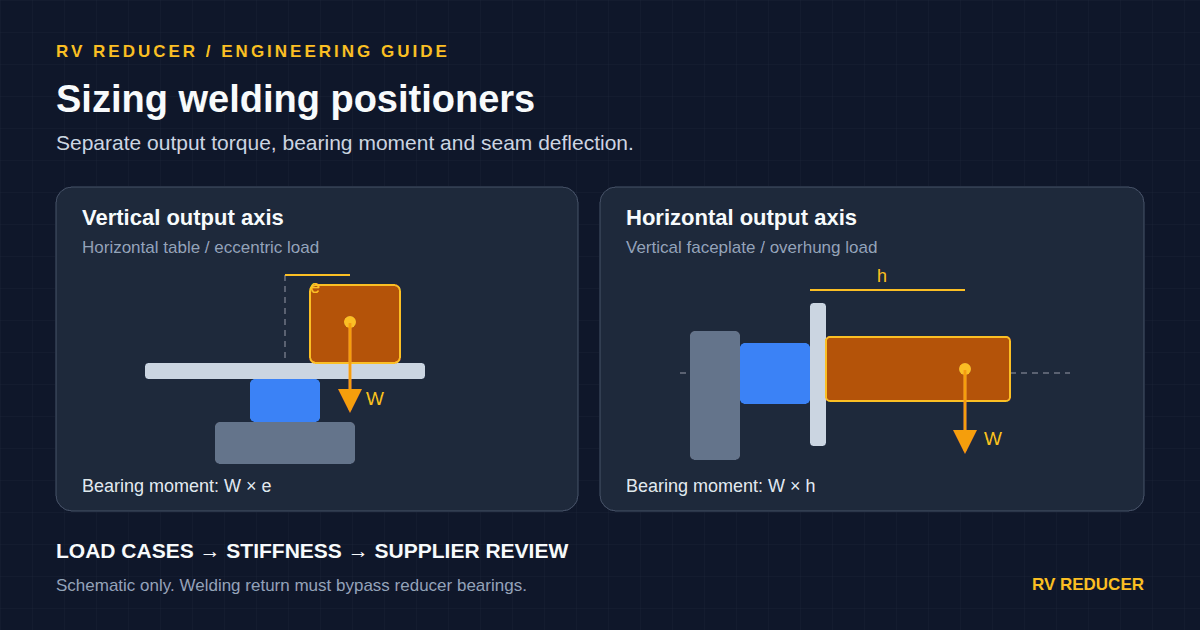
Let z be the output rotation axis. Define the composite CoG relative to the supplier's bearing reference datum as r = (e_x, e_y, h) in meters; e = √(e_x² + e_y²) is radial eccentricity and h is axial overhang. With gravity force F expressed in that same coordinate system:
Weight:                 W = m × g                       [N]
Moment at the datum:    M = r × F                       [N·m]
Output-axis torque:     T_z = M_z                       [N·m]
Overturning moment:     M_k = √(M_x² + M_y²)              [N·m]
Axial / radial force:   F_a = |F_z|; F_r = √(F_x² + F_y²) [N]
Use the supplier's defined reference datum, load signs and combined-load method. The faceplate surface and the bearing reference plane may differ.
For a horizontal table with vertical output axis, F = (0, 0, −W): axial force is W, overturning moment is W × e, and gravity torque about the output axis is zero.
For a vertical faceplate with horizontal output axis, choose F = (0, −W, 0): radial force is W, overturning moment is W × |h|, and gravity torque magnitude is W × |e_x|. Do not add the eccentric gravity torque to the bearing's transverse bending moment.
Across unrestricted orientations, W × √(h² + e²) is a conservative gravity-only upper bound on overturning moment. The largest bending and largest output torque need not occur at the same orientation. Evaluate the actual tilt and rotation envelope.
2.2 Normal Stops and Emergency Stops
For a constant-deceleration screening model:
ω = 2π × n / 60              [rad/s, with n in rpm]
α_stop = ω / t_stop          [rad/s²]
T_inertia = J_axis × α_stop  [N·m]
Combine gravity, inertia and friction with their signs for each load case. An eccentric point mass also creates tangential force m × α × e and centripetal force m × ω² × e; their axial overhang can create additional bending. A full rigid-body model must include the inertia tensor and coupled motion of both axes.
Obtain the drive's actual stopping profile, brake engagement timing and permitted stop count. A motor holding brake is not automatically rated for dynamic emergency braking. Compare normal duty, acceleration and emergency loads with their corresponding supplier limits and allowed durations. There is no universal 2× emergency-stop multiplier.
3. Moment Stiffness vs. Backlash: Calculating Weld-Seam Offset
Moment stiffness K_m relates transverse bending to flange tilt. Torsional stiffness and backlash describe behavior about the output axis; they are separate specifications.
3.1 Convert Flange Tilt into a Seam Error Budget
θ_tilt = M_k / K_m                            [arcmin]
θ_rad = θ_tilt × π / 10,800                    [rad]
δ_seam ≈ d_perp × θ_rad                       [mm]
Use matching units: M_k in N·m requires K_m in N·m/arcmin. Here d_perp is the perpendicular distance in millimeters from the tilt axis to the seam point. For a general 3D seam, use the displacement vector δ = θ × r_seam; faceplate radius alone may not capture the axial lever arm.
This is a small-angle estimate of the reducer's contribution. Fixture, arm, base, mounting joint and robot compliance also consume the seam-error budget. Load-dependent stiffness may require a supplier curve rather than one constant.
3.2 Hypothetical Stiffness Comparison
Assume M_k = 12,000 N·m and d_perp = 1,400 mm. These are illustrative stiffness values, not specifications for named reducer models:
- Candidate A:
K_m = 9,800 N·m/arcmin; tilt1.224 arcmin; seam displacement approximately 0.499 mm. - Candidate B:
K_m = 21,000 N·m/arcmin; tilt0.571 arcmin; seam displacement approximately 0.233 mm.
For an assumed 0.35 mm reducer-only allocation, A exceeds the allocation and B passes this one check. Neither result establishes weld quality or validates the complete positioner. Ask the supplier for the stiffness test method, load range, mounting conditions and other compliance contributions.
4. Architectural Comparison: Six Positioner Classes
These are load-path comparisons within this guide's scope, not payload ratings. Manufacturer series names and flange sizes do not establish interchangeability.
| Positioner architecture | Typical load path | Main sizing question | Evidence to request |
|---|---|---|---|
| Horizontal headstock / tailstock | Radial reactions shared between supports; drive torque at the headstock | What bearing reactions and residual bending reach the reducer? | Support spacing, alignment, fixture flexibility and reaction calculation |
| Vertical-axis rotary turntable | Axial weight plus eccentric bending | Are combined axial load, moment and duty within the bearing limits? | CoG map, combined-load curve and bearing-life calculation |
| L-type tilt and rotate | Rotary-axis loads vary with tilt; tilt axis carries the moving assembly | Which axis is limited by sustained gravity torque, bending or stiffness? | Separate torque and bearing-load histories for both axes |
| C-frame / skyhook | Hanging load plus bending and cyclic joint loads | Can the flange and bolted joints carry the full load envelope? | Joint design, preload, flange stiffness and fatigue review |
| Drop-center positioner | Reactions depend on frame and support layout; drives may be single or dual | How are loads shared without excessive drive fighting? | Support model, synchronization strategy and alignment tolerance |
| Ferris wheel / dual station | Main sweep axis carries both stations; local axes carry their fixtures | What happens at worst imbalance and during each stop? | Station mass combinations, inertia, stop profile and brake checks |
5. Worked Screening Calculation: L-Type Positioner with a 1,500 kg Workpiece
This reproducible example demonstrates which requirements can be calculated and which remain open. It does not select a catalog model.
5.1 Assumed Inputs and Exclusions
- Workpiece mass: 1,500 kg; fixture mass: 500 kg; combined mass: 2,000 kg.
- Gravity:
g = 9.81 m/s²; weight:W = 19,620 N. - Rotary-axis CoG:
h = 0.65 m; radial eccentricity:e = 0.35 m. - Tilt-axis geometry for this example: CoG projection in the plane perpendicular to the tilt shaft is
(1.10 m, 0.35 m), with1.10 = 0.45 + 0.65 mfrom aligned arm and overhang dimensions. This geometry must be checked against CAD. - Rotary-axis inertia:
J_rot = 450 kg·m², assumed about that axis and including the rotating table. - Rotary-axis speed: 5 rpm; normal acceleration: 0.5 s; assumed emergency deceleration: 0.15 s.
- Tilt-axis inertia, axial offset from its bearing datum, support reactions, friction and the masses of the arm and rotary reducer are not supplied. Their omission prevents final sizing of the tilt axis.
5.2 Rotary Axis: Bearing Bending and Output Torque
Horizontal table:  M_k = 19,620 × 0.35 = 6,867 N·m
Vertical faceplate: M_k = 19,620 × 0.65 = 12,753 N·m
All-orientation gravity bound:
M_k ≤ 19,620 × √(0.65² + 0.35²) = 14,484 N·m (rounded)

Maximum gravity torque: |T_g| ≤ 19,620 × 0.35 = 6,867 N·m
Speed: ω = 2π × 5 / 60 = 0.5236 rad/s
Normal inertia torque: 450 × 0.5236 / 0.5 = 471 N·m
Assumed stop inertia torque: 450 × 0.5236 / 0.15 = 1,571 N·m
Conservative torque sums, excluding friction:
Normal acceleration: 6,867 + 471 = 7,338 N·m
Assumed stop:        6,867 + 1,571 = 8,438 N·m
The 14.48 kN·m figure bounds gravity bending only; it does not include dynamic bearing loads. If a buyer applies an illustrative 2.0 screening allowance to that bound, the resulting request is 28.97 kN·m, not a calculated emergency-stop load or an approved fatigue margin. The supplier must check actual load combinations and duty.
The 6.87 kN·m gravity torque may persist while welding in a tilted orientation. Passing only an acceleration or emergency torque limit is insufficient; check sustained duty and thermal capability as well.
5.3 Tilt Axis: Gravity Torque Is Not Bearing Overturning Moment
The assumed CoG projection gives a maximum gravity lever arm of:
r_perp = √(1.10² + 0.35²) = 1.1543 m
|T_g,tilt|max = 19,620 × 1.1543 ≈ 22,648 N·m = 22.65 kN·m
This is torque about the tilt shaft. It is not a 22.65 kN·m transverse bearing moment. The tilt bearing moment requires the missing axial offset, support geometry and all assembly masses. The tilt emergency torque also requires its own inertia and stopping profile; the rotary-axis inertia cannot be reused.
5.4 Supplier Verification Matrix
| Check | Rotary axis screening result | Tilt axis screening result | Required supplier evidence |
|---|---|---|---|
| Sustained gravity torque | Up to 6.87 kN·m | Up to 22.65 kN·m for the stated partial mass model | Duty-dependent torque and thermal limits |
| Normal acceleration torque | Up to 7.34 kN·m before friction | Open: tilt inertia and motion profile missing | Allowed acceleration torque and duration |
| Emergency torque | Up to 8.44 kN·m for the assumed stop | Open: tilt stop case missing | Emergency limit, permitted cycles and brake timing |
| Gravity overturning moment | Bound 14.48 kN·m across orientations | Open: axial offset and supports missing | Combined-load limits at the specified datum |
| Axial and radial forces | Each can reach 19.62 kN in different orientations | Requires complete assembly and support model | Bearing reactions and combined-load calculation |
| Moment stiffness | Derive from the allocated seam error | Check both reducer and arm compliance | Measured stiffness curve and mounting conditions |
| Bearing life | Not established by a static margin | Not established | Load spectrum, speed, lubrication and life model |
| Welding current protection | Dedicated rotary return required | Review conductive paths across both axes | Rated return device and installation verification plan |
Procurement decision: keep the model selection open until these checks are supported by the exact supplier datasheet and application review. A nominal frame number or a peak torque multiplier cannot approve this positioner. Send the load cases for a sizing review, including the missing tilt-axis data.
6. Electrical Arcing Protection: Keep Welding Return Current Out of Bearings
A welding return circuit that crosses rolling contacts can cause electrical pitting and lubricant damage. A dedicated rotary return device provides a path from the workpiece back to the welding power source without using the reducer bearings as conductors.
6.1 Define the Complete Welding Return Path
Specify the path workpiece → rated rotary current collector → welding power source return terminal. Check every rotating and tilting interface, including clamps, support bearings, utilities and station-transfer mechanisms. The 500 A labels in the diagram are illustrative, not a device rating.
Electrical erosion can produce pitting and corrugation patterns, but appearance alone does not identify the root cause. Inspect the return contacts and investigate alternate current paths before replacing a damaged bearing.
6.2 Safeguards to Include in the RFQ
- Rated rotary return device: Specify welding current, waveform, duty cycle, rotation speed, contact wear allowance, cable routing and maintenance access. Confirm current capacity and contact heating with the device manufacturer.
- Engineered isolation where required: If the design uses an insulated fixture interface, review every conductive fastener and utility path. Check insulation durability together with bolt preload, creep and structural stiffness; an insulating plate alone does not validate the circuit.
- Protective bonding and commissioning: Keep protective earth bonding as a separate safety function. Do not remove it to redirect welding current. Have the responsible electrical engineer define continuity, insulation and live-load checks using the equipment instructions and applicable requirements. This guide specifies no universal resistance or voltage-drop acceptance threshold.
7. Thermal Limits, Lubrication, and Weld Spatter Sealing
7.1 Evaluate the Actual Duty Cycle
Record welding rotation, acceleration, indexing and dwell times, with torque and speed for each segment. Motion duty is ED% = total motion time / total cycle time × 100%, but that percentage alone cannot establish thermal capacity. Include loaded holding periods, ambient heat and radiation from preheated parts. Confirm housing-temperature limits and sensor locations against the exact reducer documentation.
7.2 Use the Model's Approved Lubricant and Service Instructions
Request the approved lubricant, fill quantity for the mounting orientation, compatibility restrictions and service interval. A named grease used in another RV model is not proof of compatibility. Do not assume a universal 20,000-hour grease life or mix lubricants without written approval. Heat shields or a cooled interface may be appropriate where a thermal review identifies excessive heat transfer.
7.3 Protect Seals Without Changing the Bearing Interface
Use a spatter deflector or labyrinth cover to keep hot particles and grinding dust away from seal lips. Select seal materials with the supplier based on temperature, grease compatibility and shaft conditions. Review any added adapter for stiffness, alignment, heat transfer and maintenance access.
8. Sourcing and RFQ Engineering Checklist
Provide these inputs so a supplier can identify missing information before quoting a model:
- Mass inventory: Workpiece, fixture, faceplate, moving arm, reducer and attached equipment for every station combination.
- CoG and bearing datums: 3D coordinates and support geometry at each axis; mark the supplier reference planes on CAD.
- Motion envelope: Tilt angles, rotary travel, weld seam coordinates and continuous-rotation requirements.
- Inertia and duty: Inertia about each axis, speed, acceleration, loaded dwell, indexing and cycle counts.
- Stop and brake cases: Validated stopping profiles, brake location, engagement timing and permitted emergency cycles.
- Error allocation: Maximum reducer-induced seam displacement, moment stiffness, torsional stiffness and lost motion.
- Welding circuit: Current, waveform, duty cycle, rotary return rating, isolation design and protective bonding plan.
- Thermal environment: Ambient and radiant heat, approved lubricant, seal protection and maintenance access.
- Interfaces and utilities: Flange geometry, fastener design, hollow bore, rotary unions and electrical slip rings where needed.
- Acceptance and commercial terms: Exact model and ratio, datasheet revision, signed load review, inspection reports, documentation language, warranty, lead time and spare-parts support.
9. Frequently Asked Questions
Can I size a welding positioner using motor torque formulas alone?
No. Check output torque and its duty separately from axial force, radial force, overturning moment and bearing life. A motor torque calculation does not establish the load capacity or stiffness of the reducer's output support.
Why does moment stiffness matter if backlash is already under 1 arcmin?
Backlash describes play about the output axis. Moment stiffness governs transverse flange tilt. With an effective seam lever arm of 1,200 mm, 1.5 arcmin of tilt produces about 0.524 mm displacement. Compare that contribution with the actual error allocation; it does not by itself predict weld defects.
Does an emergency stop always double the reducer load?
No. The inertia term depends on speed and actual deceleration, while gravity torque depends on orientation. Brake timing and structural flexibility also matter. The 0.15 s stop in this guide is an example input, not a general stopping requirement.
What helps prevent welding current from damaging the reducer?
Use a properly rated rotary return device connected to the welding power source return. Review all alternate conductive paths across both axes. Engineered insulation may be needed, while protective earth bonding remains intact. Define acceptance tests with the electrical engineer and equipment manufacturers.
Should I choose a hollow-shaft or solid-shaft RV reducer?
Choose a hollow bore when utilities need that route, then compare the exact models' load and stiffness data. A hollow bore alone does not permit unlimited rotation: hoses may need rotary unions and cables may need slip rings. Solid-shaft designs are not universally stiffer or cheaper. Nabtesco's RV series page identifies a solid-shaft component-set family; it does not establish cross-brand equivalence.
How often should positioner reducer grease be replaced?
Follow the exact model's service manual and approved lubricant requirements. Adjust the maintenance plan for actual temperature, contamination, duty and inspection results. Request a written interval and sampling plan rather than applying an unsupported universal hour count.
10. Next Steps: Turn Positioner Load Cases into an Engineering RFQ
Review the robot turntable application requirements or welding robot reducer applications. For related joint calculations, see the heavy-payload robot RV reducer selection guide.
For a project review, send your mass inventory, fixture CAD, CoG coordinates, inertia, motion and stop profiles, seam-error budget and welding return concept. Contact the RV Reducer team to discuss candidate models, available supporting calculations, quotation scope and lead time.
Sources / References
Source review date: October 30, 2026. The references support the scope stated below. The worked calculations are this article's hypothetical analysis; none of these sources certifies the example or supplies its assumed stiffness values.
- Nabtesco Motion Control — Engineering: Cycloidal Gear Technology. Manufacturer overview supporting the description of two-stage RV construction and integrated support bearings. This is an overview, not the claimed model-specific selection manual.
- Nabtesco Precision Europe — RV cycloidal gearbox with solid shaft. Manufacturer product-family description, including welding positioner and rotary-table applications. Obtain current model documentation for actual torque, bearing and stiffness limits.
- International Organization for Standardization — ISO 10218-2:2025, Robotics — Safety requirements — Part 2: Industrial robot applications and robot cells. Public catalog summary identifies the robot-cell safety scope. It provides no reducer rating, universal seam tolerance or bearing-current threshold.
Author

Categories
More Posts
Cycloidal vs. Planetary Wheel Drives for Heavy AMRs and AGVs: Sourcing and Sizing Guide for 1–5 Ton Payloads
Compare cycloidal vs. planetary wheel drives for 1–5 ton AMRs and AGVs. Check wheel loads, sizing and supplier evidence, then prepare an engineering RFQ.
Predictive Maintenance for RV Reducers: A Buyer's and Engineer's Guide to Condition Monitoring
Discover how vibration analysis and thermal imaging can detect RV reducer degradation hours before failure, reducing TCO and unplanned downtime.
Hollow Shaft RV Reducers: Engineering and Sourcing Guide for Internal Cable Routing
Discover how hollow shaft RV reducers solve high-density wiring challenges in modern robotics. A complete guide on torque ratings, bore sizing, and procurement.