
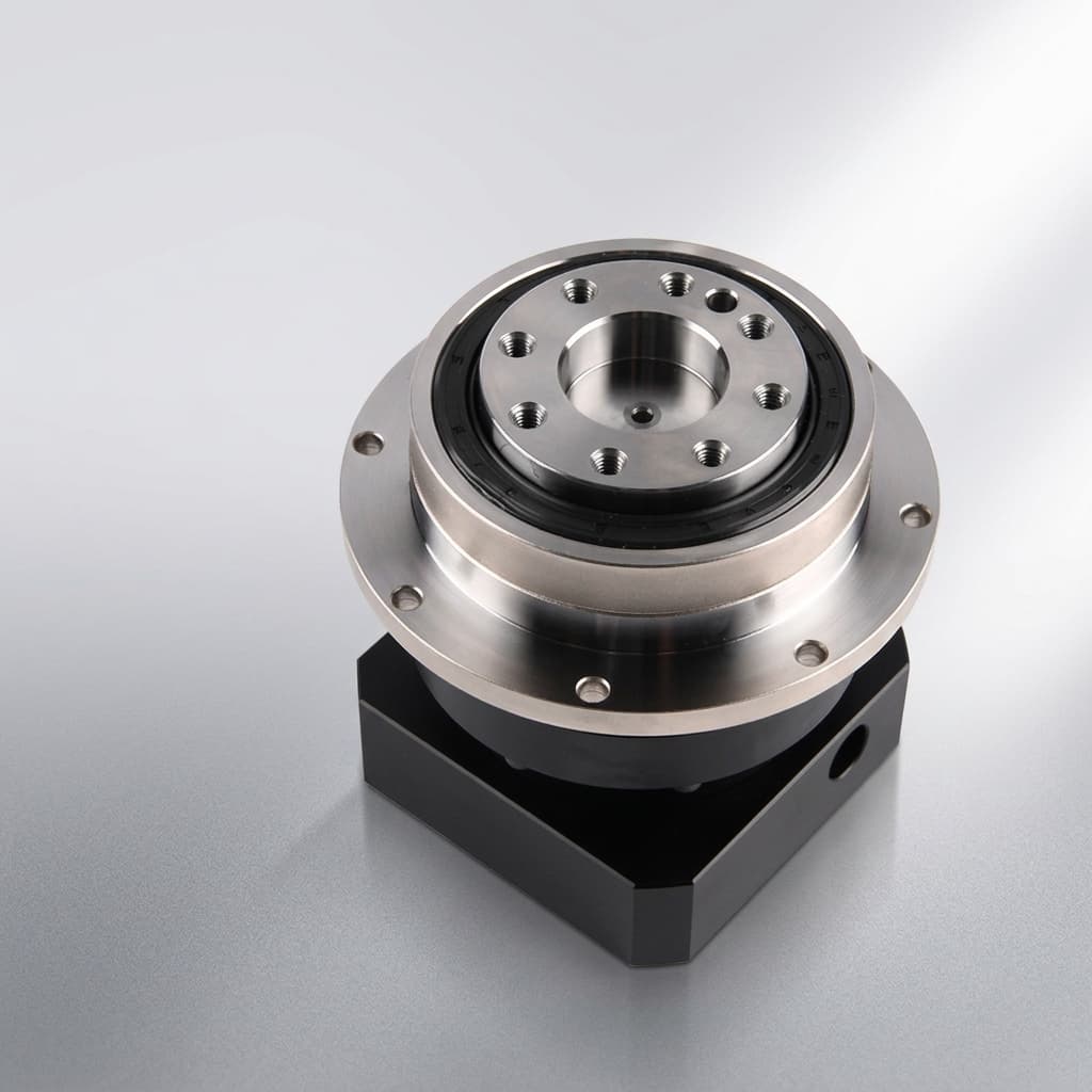
RV Reducer Thermal Rating and Duty Cycle (ED%) Sizing: Preventing Overheating, Grease Breakdown, and Seal Failure in 24/7 Automation
Check RV reducer thermal rating and duty cycle (ED%) with a worked heat-loss example, lubricant limits, and a practical FAT checklist. Prepare your engineering RFQ.
RV reducer thermal rating must be checked alongside torque, speed, and duty cycle (ED%). A reducer can satisfy its mechanical load limits while generating more heat than its installed housing and machine frame can release. For 24/7 automation, selection therefore needs both a complete motion profile and evidence that temperature stabilizes within the selected manufacturer's limits.
This guide helps mechanical engineers, automation integrators, and procurement teams distinguish a catalog speed limit from an approved continuous operating point. It provides a reproducible heat-loss example, a component review matrix, and a factory acceptance testing (FAT) checklist. These support an engineering RFQ; they do not certify a particular reducer model.
For the mechanical checks, use our heavy payload robot reducer selection guide and lost motion and backlash sizing guide. For a supplier review, send your motion profile, mounting arrangement, and worst-case ambient temperature.
Engineering and procurement takeaways
- Calculate ED% from the whole repeating cycle, but retain the torque and speed history: equal duty factors can produce different heat loads.
- Apply the temperature and lubrication requirements for the exact reducer, ratio, and installation. A limit from one manufacturer's catalog is not a universal industry rule.
- Use loss data at the relevant load and speed. Maximum speed, motor RMS torque, and equivalent fatigue torque do not independently establish thermal capacity.
- Require an agreed stabilization criterion and a recorded temperature curve. A fixed two-hour run does not automatically demonstrate equilibrium.
- Confirm lubricant, seal, and cooling changes with the reducer supplier before approving them.
1. Scope, Operational Boundaries, and Content Date
Published and content reviewed: November 6, 2026. Region: Global; language: English. This guide covers precision two-stage RV cycloidal reducers in robot joints, rotary indexers, positioners, and automated assembly equipment. It addresses thermal screening and purchasing evidence, rather than selecting a specific frame size from a universal derating chart.
The worked example assumes repeated cycles in an ordinary factory installation, with a defined mounting frame and ambient air temperature. Vacuum service, washdown, cleanrooms, corrosive atmospheres, nearby furnaces, and unusually small oscillation angles require separate application review. Include motor heat transfer and the final enclosure in that review.
Evidence boundary: Manufacturer statements are linked and limited to the products described in their source. All numerical loss inputs and thermal conductance values in the worked example are hypothetical assumptions, not factory measurements or model ratings. No customer endurance test or measured cooling improvement is claimed. Obtain the current manual and written supplier confirmation before release.
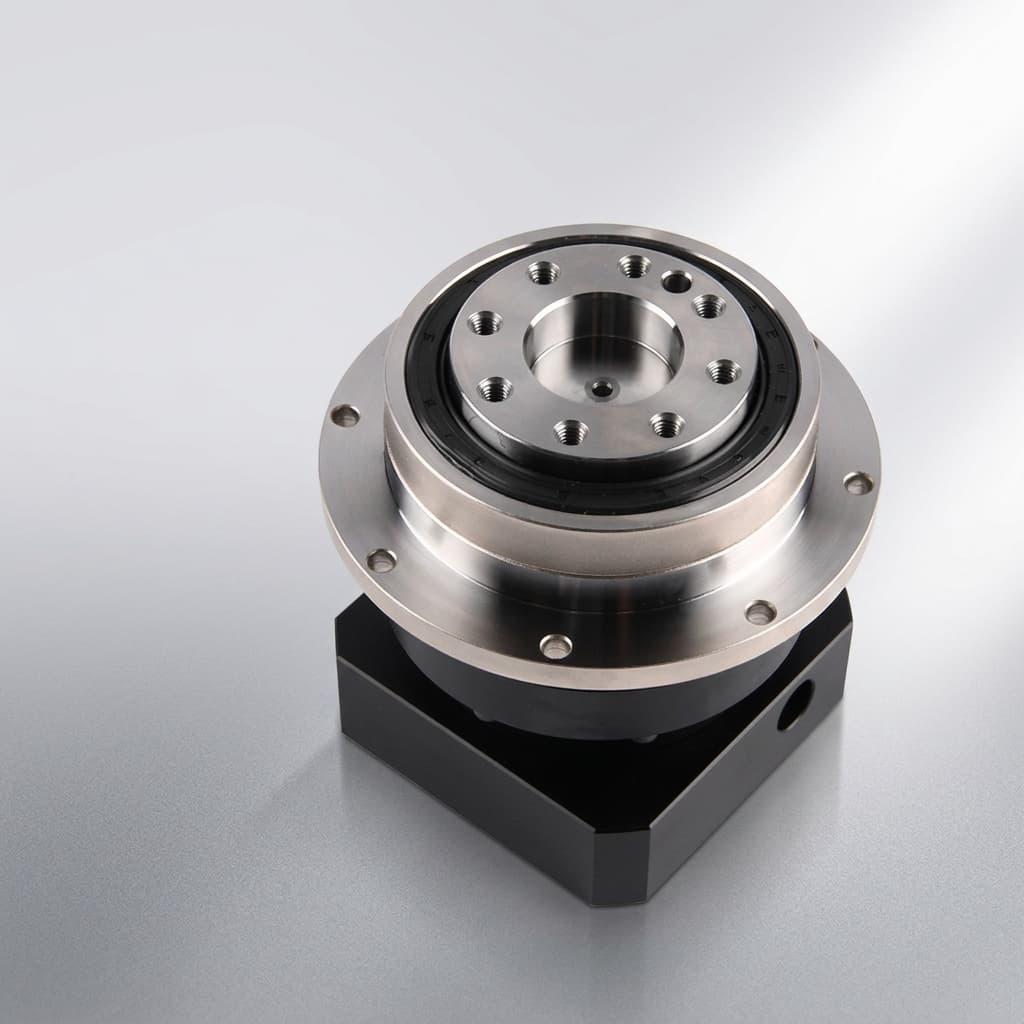
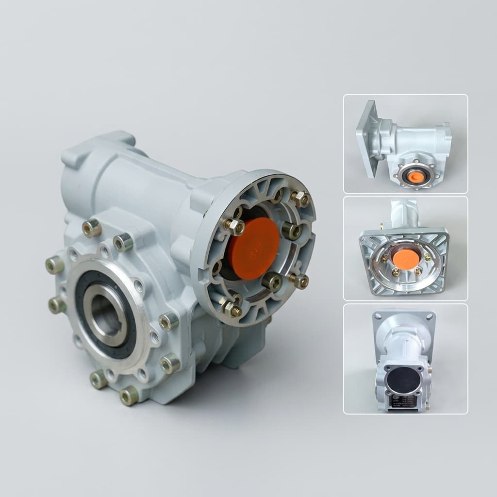
Product illustration only; the image does not identify a tested thermal rating or the reducer used in the calculation.
2. Why Mechanical Capacity and Thermal Rating Need Separate Checks
2.1 Mechanical selection remains necessary
Check the supplier's specified equivalent load method, allowable acceleration and deceleration torque, emergency-stop torque, speed, external moments, and bearing loads. A simple arithmetic average of torque can hide damaging peaks. Likewise, a motor RMS torque calculation primarily addresses motor heating and cannot replace the reducer manufacturer's fatigue calculation.
Thermal screening is an additional check. A lightly loaded axis running quickly can produce appreciable churning, bearing, and seal losses. A heavily loaded axis moving briefly may instead be governed by contact fatigue or peak torque. Neither failure mechanism can be dismissed from duty factor alone.
2.2 Where the heat comes from
Nabtesco's engineering explanation describes its RV mechanism as a spur-gear first stage driving crankshafts and paired cycloidal gears in the second stage. In this type of mechanism, mesh friction, bearings, lubricant movement, and rotating seals all contribute to mechanical loss.
For a steady motoring segment, a useful power balance is:
P_in = T_in × n_in / 9550                  [kW; N·m and rpm]
P_loss = P_in - P_out = P_in × (1 - η)    [kW]
Efficiency η must correspond to the actual load, speed, lubricant, and temperature. If input power is assumed to be 3.5 kW and efficiency is assumed to be 0.88, the calculated loss is 0.42 kW, or 420 W. This arithmetic does not establish the loss of an RV-160E or any other named model.
Near zero transmitted power, a constant-efficiency approximation becomes unreliable because friction can remain significant. During deceleration, torque and speed signs also matter. Use a consistent bidirectional energy balance or a supplier loss map; do not average negative mechanical power as if it were negative frictional heating. Electrical power at the drive includes motor and inverter losses and is not a direct measurement of reducer heat.
2.3 A traceable manufacturer reference
The Nabtesco RV Series catalog, printed pages 80–81 and 114 provides these boundaries for its covered products:
- It specifies a maximum operating reducer surface temperature of 60°C and warns that load, duty ratio, and ambient conditions can require cooling or reduced speed.
- Its glossary defines allowable output speed under no load, rather than as a guarantee for continuous loaded operation.
- It lists a standard lubricant replacement interval of 20,000 hours, with earlier condition checks and replacement as necessary when the reducer surface exceeds 40°C.
These are manufacturer-specific instructions. They do not establish a universal core-to-casing temperature offset, a grease oxidation failure temperature, or an interchangeable rating for another supplier's reducer. A housing measurement alone cannot reveal the hottest internal contact temperature.
3. Duty Cycle (ED%) and Thermal Equilibrium Calculations
3.1 Record the full cycle
For the motion-based definition used here:
ED% = (t_acc + t_const + t_dec) / t_cycle × 100%
t_cycle = total moving time + total dwell time
Include every move in the repeating sequence, including returns and low-speed positioning. Identify whether a supplier uses a different duty definition. Distinguish a machine available for 24 hours per day from a reducer that actually rotates continuously.
Retain segment duration, input speed, output torque, direction, and dwell state. For a speed summary, use magnitudes so that a reversing axis does not misleadingly average to zero:
n_avg,abs = Σ(|n_j| × t_j) / t_cycle [rpm]Use an integral or sufficiently fine sampling for acceleration ramps. This average is a profile descriptor, not a thermal approval criterion. Two profiles at 50% ED can have different speeds, torque peaks, and cycle lengths; a long uninterrupted move may create a higher temperature excursion than many short moves with the same overall moving fraction.
3.2 Estimate average heat, not just average speed
If segment loss estimates are available:
P_loss,avg = Σ(P_loss,j × t_j) / t_cycle [W]Obtain these estimates from supplier data or calibrated tests wherever practical. Record any assumption used for uncharacterized segments. At stationary dwell, shaft power can be zero while the motor still heats the mounting flange. Treat that incoming heat separately from reducer mechanical loss.
For an initial installation-level screen, a lumped thermal model is:
C_th × dT_case/dt = P_loss + Q_external - G_eff × (T_case - T_ambient)
At steady state: T_case ≈ T_ambient + (P_loss,avg + Q_external,avg) / G_eff
Here, C_th is effective thermal capacitance in J/K and G_eff is effective thermal conductance in W/K. G_eff represents the combined housing, airflow, radiation, and mounting paths around the evaluated operating point. It must come from a justified model or representative testing; multiplying flange area by the thermal conductivity of aluminum is not sufficient.
A single ambient temperature is a simplification. If the mounting frame and surrounding air run at different temperatures, model those paths separately. The steady-state calculation also cannot establish transient peak temperature. When predicted equilibrium exceeds the permitted limit, reject that operating point pending redesign or validation; it does not automatically prove an unstable thermal runaway mechanism.
3.3 Worked example: a 12-second indexing cycle
Hypothetical calculation, not a reducer catalog table. The following mean losses are invented inputs to demonstrate the method. Acceleration, transfer, deceleration, return, and low-speed settling total nine seconds, giving ED = 9 / 12 × 100% = 75%.
| Cycle segment | Duration (s) | Assumed mean reducer loss (W) | Heat per segment (J) |
|---|---|---|---|
| Acceleration | 2 | 160 | 320 |
| Loaded transfer | 3 | 220 | 660 |
| Deceleration | 1 | 120 | 120 |
| Stationary dwell | 3 | 0 | 0 |
| Return move, including ramps | 2 | 140 | 280 |
| Low-speed settling move | 1 | 20 | 20 |
The energy total is 1,400 J. Average reducer loss is therefore 1,400 / 12 = 116.7 W. For this example only, assume no incoming motor heat and an installed G_eff of 5 W/K. The predicted steady temperature rise is 116.7 / 5 = 23.3 K.
At 25°C ambient, predicted casing temperature is 48.3°C. At 40°C ambient, it becomes 63.3°C. If the selected unit's approved surface limit is 60°C, the hotter installation fails this preliminary screen despite having the same ED%, torque, and speed profile.
At the hotter ambient, the assumed heat rejection at that limit is 5 × (60 - 40) = 100 W. This is less than the estimated loss. An independently established G_eff of 7 W/K would predict 56.7°C, but the example does not claim that adding a particular fan achieves that conductance. Measurement uncertainty and the required design margin still need review.
4. Visual Guide: From Motion Profile to Thermal Approval
This schematic shows the decision path. It is not a measured temperature map or a duty-to-speed rating curve.
5. Component Thermal Risks and Evidence to Request
Temperature limits belong to the assembled product and its approved components. Generic material labels such as NBR or FKM cannot establish the continuous capability of a complete reducer.
| Component or interface | Thermal concern | Evidence to request | Engineering response |
|---|---|---|---|
| Approved lubricant | Oxidation, viscosity change, oil separation | Exact grade, fill quantity, maintenance instructions | Match the supplier specification and trend condition |
| Input shaft seal | Friction, local lip heating, shaft wear | Seal compound, shaft finish, speed and pressure capability | Review the complete sealing arrangement |
| Static seals and housing joints | Expansion, leakage, chemical compatibility | Gasket or O-ring specification and lubricant compatibility | Inspect joints hot and after cooldown |
| Crankshaft bearings | Lubrication film and preload changes | Bearing arrangement and application load assessment | Check noise, vibration, and running torque trends |
| Cycloidal gears and pins | Contact conditions and changing clearances | Supplier load/life calculation and inspection criteria | Retain mechanical fatigue checks alongside thermal checks |
| Output bearing and mounting flange | Thermal growth, load transfer, positioning drift | Bearing limits, mounting tolerances, hot-state accuracy results | Verify the installed assembly at operating temperature |
| Motor adapter and enclosure | Incoming heat and restricted heat rejection | Motor temperature, flange design, enclosure airflow | Reproduce these boundary conditions in validation |
Use this matrix to identify missing documents before sample approval. A supplier quoting only a grease temperature range has not established seal performance, bearing life, or hot-state positioning accuracy.
6. Continuous Speed Derating: What Can Be Approved?
There is no universal ED%-to-rpm conversion for all RV-E and RV-C reducers. A square-root duty correction or a fixed percentage of maximum input speed needs a validated loss model before it can be used. Size, ratio, load, lubricant, and installation can all change the relationship between speed and heat.
Ask the supplier to identify whether a catalog number describes input or output speed, no-load operation, a rated life point, or a conditional application limit. Use the correct overall ratio for the installed mechanism. Then request the allowable operating envelope for the actual torque-speed-time profile and ambient conditions.
If the supplier cannot provide a thermal map, agree on representative testing before production approval. Start within documented mechanical and thermal limits and define stop criteria. Do not increase speed until a casing limit is reached and call that a rated endurance test. A larger frame, a different ratio, or a different drive arrangement may be appropriate, but each candidate needs its own loss and heat rejection assessment.
For help comparing supplier responses, request a review with the cycle table and the proposed reducer identification. Include unresolved assumptions so the response can distinguish a preliminary estimate from an approved application.
7. Lubrication, Grease Life, and Seal Leakage
7.1 Select the approved formulation and fill
Nabtesco's lubricant product listings identify VIGO grease, RV Grease LB00, Molywhite RE No. 00, and RV Oil SB150 as distinct products. Their presence in a supplier's range does not mean they can be substituted in every reducer.
Specify the exact approved lubricant, quantity, orientation-dependent filling procedure, and change method. Do not infer compatibility from a shared thickener name or viscosity grade. For topping up or changing brands, obtain written compatibility and flushing instructions. Excess fill can increase churning; insufficient fill can leave contacts inadequately supplied. A generic percentage fill rule is not an adequate substitute for the assembly instructions.
7.2 Maintenance intervals need operating evidence
Heat can accelerate lubricant degradation, but an assumed “life halves every 10°C” rule is a sensitivity heuristic, not a grease replacement schedule. A casing sensor does not measure the lubricant's complete temperature history or local contact conditions. Water, particles, shear, and additive depletion also matter.
Use the manufacturer's maintenance baseline, then agree how hotter service changes inspection and replacement. Record operating hours, measured temperature, lubricant identity, leakage, and any condition findings. Compare successive samples using a consistent method if sampling is approved. Appearance alone cannot establish remaining useful life, and a nominal interval does not guarantee uninterrupted service in every 24/7 installation.
7.3 Treat pressure as an application variable
For an idealized sealed, rigid cavity with a fixed quantity of air, heating from 20°C to 60°C gives:
ΔP = P_initial × (T_hot / T_initial - 1)
   = 1.013 × (333.15 / 293.15 - 1)
   ≈ 0.138 bar = 13.8 kPa
Temperatures in this equation are kelvin. This is an illustrative gas calculation, not a predicted pressure for a real gearbox. Headspace, lubricant expansion, leakage, and seal design affect actual pressure. A fully sealed cavity returning to its original temperature returns to its original pressure; a cooling vacuum requires additional conditions such as gas loss while hot.
Investigate leaks through fill volume, pressure capability, seal wear, shaft condition, assembly damage, and lubricant compatibility. Neither a universal pressure threshold nor a seal-material upgrade alone explains every leak.
8. Countermeasures for High-Duty Overheating
Reduce losses where possible. Revisit unnecessary high-speed returns, peak torque, and the motion sequence. Smoothing acceleration can change losses, but a longer move may increase moving time. Recalculate the entire cycle instead of assuming that an S-curve always reduces average heat by a fixed percentage.
Improve installed heat rejection. Airflow and a conductive mounting path can help, subject to the actual air and frame temperatures. Check contamination protection, fan reliability, fastener loads, and mounting stiffness. Changing an adapter material or applying an interface compound can affect alignment and joint behavior; retain the specified mounting requirements.
Reconsider the reducer and ratio. Compare alternative frames using the same production profile and enclosure. More housing area can help heat rejection, while different bearings, ratios, or lubricant behavior can change losses. Avoid assuming that the next size automatically solves the problem.
Use supplier-approved system changes. Adding a breather changes contamination protection and sealing behavior. Converting grease lubrication to oil may require different seals, passages, orientation, fill levels, and circulation provisions. These are application redesigns requiring approval, rather than routine remedies triggered by an ED% threshold.
Validate the final configuration, including cooling failure behavior where cooling is necessary for operation. A successful open-bench test with a fan does not establish performance inside a sealed production guard.
9. Procurement and Factory Acceptance Testing (FAT) Checklist
Use the following items in the RFQ and acceptance plan. The project engineer and supplier should agree numerical limits and the test procedure before the run. A proposed stabilization criterion is a contract parameter, not an asserted requirement from an unverified standard.
- Identify the assembly: Record manufacturer, exact model, ratio, serial or lot number, mounting revision, motor, lubricant grade and quantity, and seal specification.
- Define production duty: Attach timestamped torque and speed data, direction changes, dwell, payload, external moment, and emergency-stop cases. State the definition of ED% being used.
- Reproduce the installation: Specify worst-case ambient, enclosure, mounting frame, orientation, adjacent heat sources, and intended airflow or cooling equipment.
- Agree instrumentation: Use calibrated contact sensors at agreed housing locations and an ambient sensor outside the heated boundary layer. Record sensor attachment, logging interval, and uncertainty. If infrared measurements are used, control emissivity and reflections.
- Agree acceptance and stop limits: Specify permitted absolute housing temperature, any temperature-rise limit, maximum test duration, and a stabilization rule. For example, propose a rise of no more than 1 K over the final 30 minutes at stable ambient, subject to supplier acceptance and measurement capability.
- Run until the agreed criterion is met: Keep the load and cooling conditions documented. A two-hour test is sufficient only if the accepted protocol and stabilization evidence support that duration. A temperature plateau must still be below the agreed limit.
- Inspect hot and after cooldown: Record leakage, noise, vibration, running torque, and the required positioning or lost-motion measurements. Follow the approved sealing test method; do not impose an arbitrary compressed-air pressure on shaft seals.
- Retain release evidence: Obtain the temperature-time data, calibration records, deviations, lubricant traceability, inspection results, and written application acceptance. Define maintenance and retest triggers for production changes.
Thermal FAT demonstrates behavior under the tested conditions; it does not establish full fatigue life or regulatory compliance. Connect it with the agreed lifetime testing and inspection plan. After changing payload, cycle rate, lubricant, enclosure, or cooling, review whether the original approval still applies.
10. Frequently Asked Questions
Is 60°C the maximum surface temperature for every RV reducer?
No. It is a limit in the cited Nabtesco catalog for its covered products. Use the selected supplier's current instructions and any stricter project requirement. At a measured 75°C, a unit covered by that instruction is outside its stated boundary; follow the agreed stop and investigation procedure rather than estimating remaining life from casing temperature alone.
Can I run at maximum catalog input speed continuously?
Only if the supplier approves that operating point for the actual load, duty, lubricant, ambient, and mounting conditions. Confirm whether the catalog value is an input or output speed and read its accompanying conditions. There is no generally valid rule that continuous speed is 40%, 50%, or any other fixed fraction of a maximum.
Does 100% ED mean full rated torque?
No. ED% describes moving time under the definition used here. A continuously rotating lightly loaded axis and a continuously rotating heavily loaded axis can both have 100% ED. Their losses, contact loads, fatigue lives, and cooling needs can differ substantially.
How does a hot factory change the sizing decision?
It reduces the temperature difference available to reject heat at a fixed housing limit. In the simplified model, that reduces allowable heat loss. It does not imply proportional speed derating because losses do not necessarily vary linearly with speed. Use the worked example as a screening method, then obtain installation-specific evidence.
Can I mix approved-looking greases or convert to circulating oil?
Obtain approval for the exact reducer and lubricant combination first. Brand names and nominal viscosity do not establish additive compatibility, seal compatibility, or an appropriate filling procedure. Oil circulation also changes the lubrication and sealing system; supplier availability of an oil product does not approve a field conversion.
Does a thermal test prove robot positioning accuracy?
No. Heat can change dimensions, preload, and friction, but the direction and magnitude depend on the whole assembly. Measure required hot-state positioning and post-cooldown lost motion separately. A stable casing temperature is evidence for one thermal condition, rather than proof of tool center point accuracy or lifetime.
11. Sources and Next Engineering Step
Sources checked November 6, 2026. These are manufacturer references, not independent certification of this website's products. Keep the catalog revision used in your project acceptance record.
- Nabtesco — RV Series product catalog: printed pages 80–81 for operating temperature and duty terminology; page 114 for lubricant maintenance. Printed page numbering differs from PDF viewer numbering.
- Nabtesco — Cycloidal gear engineering: mechanism and two-stage construction, rather than model-specific thermal derating data.
- Nabtesco — Lubricant product range: product identities, rather than blanket substitution or conversion approval.
Preparing a 24/7 automation RFQ? Send the cycle table, selected model and ratio, mounting drawing, ambient range, and required acceptance limits. Ask for the applicable operating envelope, lubricant instructions, and a thermal validation proposal. That information lets engineering and purchasing compare offers on documented conditions instead of an unsupported “continuous duty” label.
Author

Categories
More Posts
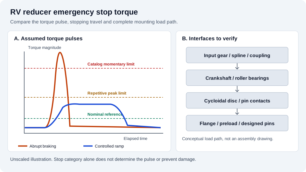
RV Reducer Emergency Stop Torque Rating, Dynamic Braking, and Peak Shock Margin: Sizing to Prevent Pin Shearing, Tooth Indentation, and Fastener Failure
Check RV reducer emergency stop torque, dynamic braking, and peak shock margin with a worked example and supplier checklist. Prepare your engineering RFQ.
RV Reducer Mounting Tolerances, Pilot Runout, and Bolt Preload: Preventing High Idling Drag, Noise, and Bearing Spalling
Review RV reducer mounting tolerances, pilot runout and bolt preload with inspection steps, a worked slip calculation and a FAT checklist. Plan your RFQ review.
RV Reducer Lost Motion, Hysteresis, and Backlash: Engineering Sizing for Torsional Rigidity, Standards Compliance, and Factory Quality Audits
Understand RV reducer lost motion, backlash and hysteresis. Estimate TCP deflection, compare test methods, and prepare an engineering RFQ with a FAT checklist.