
RV Reducer Emergency Stop Torque Rating, Dynamic Braking, and Peak Shock Margin: Sizing to Prevent Pin Shearing, Tooth Indentation, and Fastener Failure
Check RV reducer emergency stop torque, dynamic braking, and peak shock margin with a worked example and supplier checklist. Prepare your engineering RFQ.
An RV reducer emergency stop torque rating is a manufacturer-defined limit for exceptional loads, separate from nominal and repetitive acceleration torque. To size an axis, compare the worst credible output torque pulse with the selected model's documented momentary limit, duration and event allowance. Then check the motor brake, drive energy path and flange joint independently. A torque rating alone cannot establish a safe stopping distance or prevent every failure.
This guide helps mechanical designers, automation integrators and procurement teams prepare that comparison. It includes a reproducible calculation, a supplier evidence matrix and a post-event inspection plan. It does not report physical gearbox tests or field failure statistics.
For baseline mechanical sizing and integration, review our heavy payload robot reducer selection guide, mounting tolerances and bolt preload guide, and thermal rating and duty cycle guide. For a model-specific review, send your stopping load cases and interface requirements.
Engineering and procurement takeaways
- Obtain three separate ratings: nominal, repetitive acceleration/deceleration and momentary emergency torque. Do not transfer a multiplier or event count between manufacturers or product families.
- Separate response delay from deceleration: dividing initial speed by total trigger-to-standstill time can underestimate braking torque when the brake acts only after a delay.
- Check both stop behavior and torque: controlled deceleration can reduce peaks, but a longer stop may violate the machine's stopping-distance requirement.
- Verify the brake's intended use: a holding torque specification does not establish dynamic stopping energy, wear life or personnel protection capability.
- Keep abnormal events traceable: retain drive faults and torque histories; unexplained changes in lost motion, drag or flange position require investigation before release.
1. Scope, Operating Boundaries, and Industry Context
Published and editorially reviewed: November 12, 2026. Region: Global; language: English. This guide covers mechanical screening for two-stage RV cycloidal reducers in industrial robot joints, welding positioners, rotary indexing tables and similar automation axes. Review it when payload, speed, tooling inertia, brake hardware or safety stop settings change.
The method evaluates output torque and the installation load path. It does not certify a functional safety performance level, a complete robot installation or compliance with local machinery requirements. A mechanical jam is also a separate impact case: stored elastic energy and contact stiffness can dominate, making a simple speed-over-stop-time estimate inadequate.
ISO 13850:2015 addresses emergency stop function design principles and refers electrical implementation to IEC 60204-1. Neither a standard's public abstract nor this guide supplies an approved reducer torque rating. Use the editions applicable to the installation and obtain the manufacturer's exact part-number, ratio and mounting documentation.
2. Reducer Torque Hierarchy: Nominal, Acceleration, and Emergency Stop
Nabtesco's product guide, PDF page 24, distinguishes rated torque, allowable starting/stopping torque and momentary maximum allowable torque. Its momentary rating applies to exceptional events such as emergency stops and external shocks. This distinction is useful; numerical limits still depend on the selected product.
Normal running       -> T_N: rated torque under catalog reference conditions
Programmed peaks     -> T_acc: permitted repetitive start/stop load envelope
Exceptional events   -> T_em: permitted momentary load envelope

For each envelope ask: torque, speed, duration, repetitions and installation.
A momentary rating is not a material yield measurement or an infinite-life claim.
2.1 Nominal Torque
Nominal torque is tied to catalog reference speed, life and operating conditions. Compare the full duty cycle with the manufacturer's life calculation and thermal limits. Passing a momentary torque check does not compensate for excessive average loading, poor lubrication or an undersized output bearing.
2.2 Acceleration and Deceleration Peak Torque
Routine indexing peaks need their own amplitude, duration and repetition assessment. A statement such as “twice nominal torque” is incomplete without those conditions. Record the intended stops per hour and production life; frequent protective stops belong in the operating load spectrum rather than being hidden in an exceptional-event allowance.
2.3 Emergency Stop Rating and Supplier Evidence
Nabtesco's engineering overview advertises E-stop capacity of five times rated torque for its described technology. That product-family statement does not establish interchangeability or an event allowance for another supplier. Do not assume a universal 1,000-stop budget, or interpret a catalog limit as the precise onset of plastic deformation.
Use the following evidence matrix in an RFQ instead of estimating model ratings from frame numbers.
| Selection item | Evidence to request | Decision before purchase |
|---|---|---|
| Nominal torque | Model-specific rating, reference speed and life method | Verify the normal duty spectrum |
| Repetitive peak torque | Allowable torque, duration and repetition conditions | Include programmed and frequent protective stops |
| Emergency torque | Momentary rating and applicable pulse definition | Compare the worst credible transient |
| Event allowance | Permitted repetitions and inspection or replacement rules | Define a cumulative event log |
| Gear ratio and inertia | Exact ratio and input-equivalent internal inertia | Confirm drive and brake sizing inputs |
| External bearing loads | Combined radial, axial and overturning-moment limits | Check worst payload position during stopping |
| Installation interface | Bolt specification, preload method and permitted load path | Check slip, separation and fastener loading |
3. Failure Physics: What Happens Inside an RV Reducer During an E-Stop Shock?
The two-stage mechanism transmits input rotation through spur gearing and eccentric crankshafts to cycloidal elements engaging housing pins. A transient can load several interfaces at once. The following mechanisms explain inspection priorities; they are not a prediction of which component will fail first in a particular reducer.
3.1 Contact Overstress and Permanent Indentation
High local contact loading can leave permanent indentations on rolling contacts. The threshold depends on geometry, load sharing, material, hardness, residual stresses and lubrication. A single generic pressure in MPa cannot establish the safe torque of an assembled cycloidal reducer.
Increased lost motion, roughness or noise after an event warrants investigation, but does not by itself prove internal indentation. Mounting slip, bearing movement, encoder reference changes and coupling damage can produce similar symptoms. Compare measurements under the same load, temperature and fixture conditions before assigning a root cause.
3.2 Crankshaft Deflection and Bearing Damage
A shock can increase crankshaft bending and concentrate roller contact near an edge. Uneven support, housing distortion and external moments can aggravate the load distribution. Obtain the supplier's combined-load checks where these effects matter. There is no general percentage of edge loading or fixed number of post-collision operating hours that predicts failure.
3.3 Input Gear, Spline and Coupling Loading
A brake acting at the motor shaft changes the load path while the driven assembly still has kinetic energy. Review input pinion engagement, shaft keys or splines, coupling capacity and motor rotor dynamics as well as the output rating. The ideal inertia reflected from output to input is J_load / i²; that relationship alone does not calculate an impact pulse.
3.4 Mounting Bolt Slip and Dowel Pin Shearing
For a friction joint, a preliminary slip estimate is T_slip ≈ μ × sum(F_preload) × r_effective. Use a justified interface friction coefficient and effective friction radius; the latter is not automatically the bolt-circle radius. Include preload scatter, settlement and any external load that unloads the interface.
If friction is exceeded, locating pins may receive unintended shear and hole-bearing loads. Pins, fitted bolts or keys can carry torque only when the drawing explicitly defines and verifies that load path. A locating dowel is not an automatic backup safety device. The mounting and bolt preload guide provides related interface review steps.
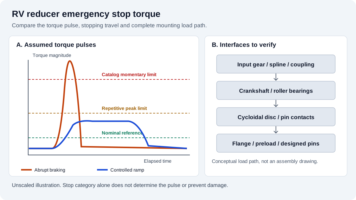
4. Engineering Diagram: Dynamic Torque Profiles and Internal Failure Zones
The schematic compares an assumed abrupt braking pulse with a controlled ramp and identifies possible stress zones. It is conceptual, not measured data or a universal comparison of stop categories. Category 0 can coast when no brake acts; Category 1 can still overload an axis if its ramp is too aggressive.
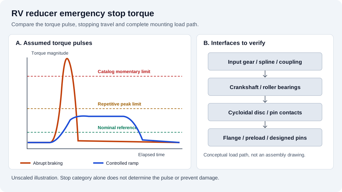
Unscaled illustration, not test data. Verify each torque envelope and the actual stopping travel for the selected axis.
5. Engineering Calculation: Peak Dynamic Braking Torque and Shock Margin
5.1 Define the Output Load and Actual Braking Interval
For a simple constant-deceleration screen, calculate:
omega_out = 2 × pi × n_out / 60              [rad/s]
alpha_magnitude = omega_out / t_decel       [rad/s²]
T_decel = J_load × alpha_magnitude + T_assist [N·m]
Here J_load is driven load and fixture inertia about the output axis, and T_assist is an external torque acting in the direction of motion during the selected stop. A resisting external torque has the opposite sign. Check both directions and all payload positions. For a robot joint, gravity torque and reflected inertia can vary with configuration.
t_decel is the interval over which speed actually decreases, excluding any initial response delay. Total stopping time also includes sensing, logic, drive and brake delays. For a non-linear speed ramp, use the trajectory's maximum angular deceleration rather than its average. The resulting flange torque screen must be supplemented by bearing loads and a more detailed dynamic model where flexibility or impact is significant.
5.2 Check Motor Inertia and Brake Capability Separately
For an ideal rigid ratio i, load inertia reflected to the motor is J_load / i². Add motor rotor and input-equivalent gearbox inertia when checking motor torque and total stopping energy. Do not add the rotor inertia to the external flange load and then count it again on the input side.
The ideal torque scaling reference for an input brake is T_brake,out,ideal = i × T_brake. Actual backdriven behavior requires a consistent power-flow model, internal inertia, friction and brake engagement dynamics. Multiplying brake torque by an assumed reverse-efficiency percentage is not a complete stopping model.
Obtain dynamic brake torque versus speed, engagement delay, allowable energy per event and cumulative wear limits. A static holding-torque value alone does not answer those questions. The Schneider Electric STO application examples illustrate why torque removal can allow coasting and why an additional brake may be required by the risk assessment.
5.3 Treat Shock Amplification as an Assumption to Validate
Compliance, lost motion and engagement transients can produce a peak above the rigid-body estimate. If a preliminary screen uses T_peak = K_shock × T_decel, record the basis and uncertainty of K_shock. It is not a catalog property or a multiplier defined by the stop category.
The worked example below uses 1.70 and 1.10 solely to show sensitivity. These are assumed inputs, not empirical recommendations. Replace them with a validated model or suitably sampled torque measurement. Motor current can support a calibrated estimate, but it also reflects rotor acceleration and drivetrain losses; it is not automatically a direct output torque measurement.
5.4 Define a Project Margin Without Calling It Certification
Calculate S_em = T_em,catalog / T_peak. A value below 1 means the estimated load exceeds the stated catalog limit. A value above 1 still requires checks on uncertainty, pulse duration, repetition, bearing loads and installation conditions.
For illustration, the example uses a project screening target of S_em ≥ 1.50. That target is an assumption, not an ISO requirement or a universal guarantee against pin shearing. Agree the required margin with the supplier and responsible machine engineer; no specific failure can be predicted from a margin of 1.3 alone.
6. Stop Category 0 vs. Stop Category 1: Behavior and Mechanical Tradeoffs
Category 0 removes actuator power immediately; Category 1 uses power for a controlled stop before removal. The Schneider Electric examples illustrate both implementations. The category does not prescribe a stopping time, shock factor or reducer life.
| Review item | Category 0 considerations | Category 1 considerations |
|---|---|---|
| Torque control | Drive torque is removed | Controlled deceleration precedes removal |
| Mechanical response | May coast or engage a separate brake | Depends on the commanded ramp and available torque |
| Stopping time | Must be determined for the actual system | Must include response delay and failure behavior |
| Reducer peak | Depends on brake and load dynamics | Depends on peak deceleration and transient response |
| Energy destination | Friction, brake or other installed paths | DC bus, resistor or regeneration where provided |
| Power or drive fault | Check gravity and residual motion | Check loss of controlled braking capability |
| Repeated stops | Assess actual load spectrum and brake wear | Assess actual load spectrum and drive heating |
Select the stop architecture through the machine risk assessment. Emergency stops, protective stops and ordinary production stops have different purposes. STO removes torque-producing capability; it does not hold a gravity-loaded axis in place or establish a safe stopping distance. A longer ramp cannot be accepted solely because it reduces gearbox stress.
For resistor-based braking, check kinetic energy, gravity work, peak power, repeated-stop average power and the drive manufacturer's resistance and duty limits. For a simple rotating load, kinetic energy is E_k = 0.5 × J × omega². Include all relevant rotating inertias and energy storage. A resistor fault can defeat the intended deceleration; the resulting behavior follows the installed fault response and must be validated. There is no universal requirement to add exactly 100% thermal margin.
7. Worked Engineering Sizing Example: Heavy Welding Turntable
Hypothetical calculation, not a customer case or bench test. Consider a tilted positioner with the following assumed parameters:
- Fixture and payload mass: 350 kg; radius of gyration: 0.32 m.
- Output load inertia:
350 × 0.32² = 35.84 kg·m². - Initial output speed: 25 rpm, or 2.617994 rad/s.
- External torque assisting motion during this short stop: 120 N·m.
- Illustrative candidate limits: nominal 1,078 N·m, repetitive peak 2,695 N·m, momentary peak 5,390 N·m. These are assumed comparison inputs, not a verified rating for a named model.
Both scenarios assume constant deceleration after brake response, approximately constant assisting torque and a rigid load. Their times exclude response delay. Brake capacity, drive capability, bearing loads and compliance remain separate checks.
Case A: assumed abrupt mechanical braking
  t_decel = 0.045 s; assumed K_shock = 1.70
  T_decel = 35.84 × (2.617994 / 0.045) + 120 = 2,205.09 N·m
  T_peak  = 1.70 × 2,205.09 = 3,748.65 N·m
  S_em    = 5,390 / 3,748.65 = 1.438

Case B: assumed controlled braking
  t_decel = 0.120 s; assumed K_shock = 1.10
  T_decel = 35.84 × (2.617994 / 0.120) + 120 = 901.91 N·m
  T_peak  = 1.10 × 901.91 = 992.10 N·m
  S_em    = 5,390 / 992.10 = 5.433
Case A misses the assumed 1.50 screening target while remaining below the assumed momentary rating. That indicates insufficient project margin, not proof of immediate damage. Case B has more estimated torque margin and is below the assumed repetitive peak rating; it does not establish infinite fatigue life or safe operation.
The peak estimate decreases by about 73.5%, but both the assumed time and shock factor changed. For the same constant-deceleration assumption, braking travel is theta = 0.5 × omega × t_decel: approximately 3.38 degrees for A and 9.00 degrees for B, before response-delay travel. This tradeoff is why torque and stopping distance must be approved together.
To turn the example into a purchase decision, replace every assumed limit with the selected supplier's data, include worst payload orientation, validate the actual stop trace and document an acceptable fault case. Request an engineering review with those inputs before freezing the reducer size or drive settings.
8. Post-E-Stop Quality Acceptance and Integrity Verification
After a collision, exceeded limit or uncharacterized hard stop, retain the event evidence and secure the machine under the approved isolation procedure. Follow the equipment and reducer manufacturer's inspection instructions before powered testing. An ordinary validated emergency stop within approved conditions does not automatically require disassembly.
The following six-stage plan defines evidence to agree before commissioning. Acceptance values come from drawings, supplier procedures and repeatable baselines, rather than universal drag percentages or lost-motion limits.
| Verification stage | Method and record | Acceptance basis | Possible concern to investigate |
|---|---|---|---|
| Event reconstruction | Save payload, speed, faults and available torque trace | Approved load and stop envelopes | Overload or unexpected brake sequence |
| Flange and interface check | Inspect witness marks, pilot condition and fasteners | Drawing limits and unchanged interface position | Joint slip, settlement or cracked parts |
| Controlled rotation check | Unload and secure the axis using the approved procedure | Supplier limits and baseline smoothness | Contact damage, misalignment or binding |
| No-load drag comparison | Repeat the baseline speed, temperature and lubrication condition | Agreed repeatability and supplier drag limits | Bearing, seal or mounting changes |
| Lost motion and vibration | Use the manufacturer's fixture, test torque and measurement method | Model-specific limits and baseline trend | Internal clearance or contact changes |
| Joint disposition and release | Inspect preload evidence; replace or retighten only as instructed | Approved fastener procedure and responsible sign-off | Preload loss, thread damage or joint distortion |
A residual tightening-torque check does not directly measure bolt preload. Likewise, the absence of an obvious vibration peak does not prove that every bearing contact is undamaged. Escalate contradictory measurements to the manufacturer instead of releasing the axis from one favorable indicator.
9. Sourcing and Commissioning Checklist: E-Stop and Dynamic Braking
Attach this checklist to the RFQ and commissioning traveler:
- Identify exact reducer model, ratio, rating revision and mounting arrangement.
- Record maximum payload inertia, center of gravity and external torque in both directions.
- Specify the stop functions and fault cases selected by the machine risk assessment.
- Separate trigger response time, brake engagement delay and actual deceleration time.
- Check maximum deceleration and travel against the approved stopping envelope.
- Obtain dynamic brake torque, energy capacity, wear limits and engagement timing.
- Verify the drive energy path, resistor duty where fitted, and fault response.
- Document the peak estimate, uncertainty and agreed project margin.
- Confirm momentary pulse and event allowances; include frequent stops in the duty spectrum.
- Check output bearings, input connections, flange slip and any designed pin load path.
- Record repeatable lost-motion, drag and interface-position baselines.
- Define event logging, inspection triggers and who authorizes return to service.
10. Frequently Asked Questions
What is the difference between acceleration torque and emergency stop torque?
Acceleration torque covers the manufacturer's permitted repetitive peak conditions. Emergency or momentary torque covers a separate exceptional-load envelope. Ask for amplitude, duration and repetitions for both. Neither can be inferred reliably from nominal torque alone, and a momentary rating is not an unlimited cyclic rating.
Does an emergency stop permanently increase lost motion?
Not necessarily. A stop within validated conditions may leave the reducer unchanged. An overload can damage contacts or interfaces, but a changed reading also has other possible causes. Compare the same fixture, applied torque, temperature and mounting condition, then investigate against the selected model's acceptance limits.
Can a servo holding brake stop a moving RV reducer load?
Only if the brake manufacturer approves the actual dynamic duty and the complete axis has been validated for it. Static holding torque does not establish allowable stopping energy, engagement shock or wear life. Some axes need an additional brake or another engineered restraint, particularly where gravity can move the load after torque removal.
How does gravity change the stopping torque calculation?
When gravity assists the initial motion, the brake must oppose both inertia and gravity during deceleration. When gravity opposes motion, it helps slow the load. Use a signed torque balance for the actual axis position and direction; do not add gravity twice if it is already included in the external torque term.
Does a braking resistor fault always trigger the motor brake?
No. The drive may lose its intended braking path or fault, but motor brake behavior depends on hardware, control logic and the configured fault sequence. Verify that sequence and any gravity-holding requirement using the drive manual and machine validation plan. A resistor rating alone does not prove the fallback stop is acceptable.
Should locating dowels carry emergency stop torque?
Only when the joint design explicitly assigns and verifies that duty. Check pin shear, hole bearing, fit, combined loading and the possibility of joint slip. Adding a harder dowel to an unverified interface can move damage into the housing. Use the reducer manufacturer's approved mounting load path.
11. Sources and Reference Boundaries
Sources checked November 12, 2026. These public references support terminology and component behavior; they do not validate the assumed numerical example or certify a machine. Obtain the applicable full standards and exact product manuals for release.
- ISO 13850:2015 — Emergency stop function: Principles for design. Official scope and standards context; not a reducer mechanical rating or a brake sizing procedure.
- Nabtesco — Precision Reduction Gear Product Guide, PDF page 24 (printed page 46), “Glossary.” Distinguishes normal, starting/stopping and momentary torque ratings. Use the relevant model's current tables and conditions for procurement.
- Nabtesco Motion Control — Cycloidal Gear Technology. Manufacturer overview of two-stage construction and advertised shock capacity. A family-level overview does not establish universal cycle limits.
- Schneider Electric — Lexium 32S: Application Examples STO. Product-specific Category 0 and Category 1 examples and coasting considerations. Follow the manual for the actual installed drive rather than copying another product's circuit.
12. Next Engineering Step and Technical Inquiry
For an RV reducer RFQ, send the payload inertia, operating speed, stop trace or proposed ramp, brake part number and flange drawing. Include the required stopping distance, expected stop frequency and worst credible power-loss case. Request written confirmation of the selected model's torque envelope, event conditions and installation requirements before approving a substitution.
For related application planning, explore hollow-shaft RV reducers for cable and utility routing, or return to the heavy-payload robot selection guide. A matching envelope or frame size is a starting point; the documented load case and mounting conditions determine suitability.
Author

Categories
More Posts
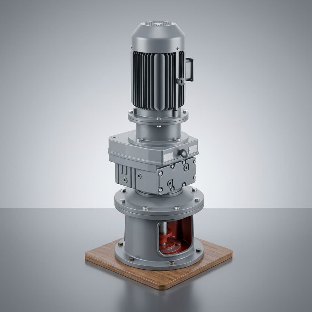
RV Reducer Mounting Tolerances, Pilot Runout, and Bolt Preload: Preventing High Idling Drag, Noise, and Bearing Spalling
Review RV reducer mounting tolerances, pilot runout and bolt preload with inspection steps, a worked slip calculation and a FAT checklist. Plan your RFQ review.
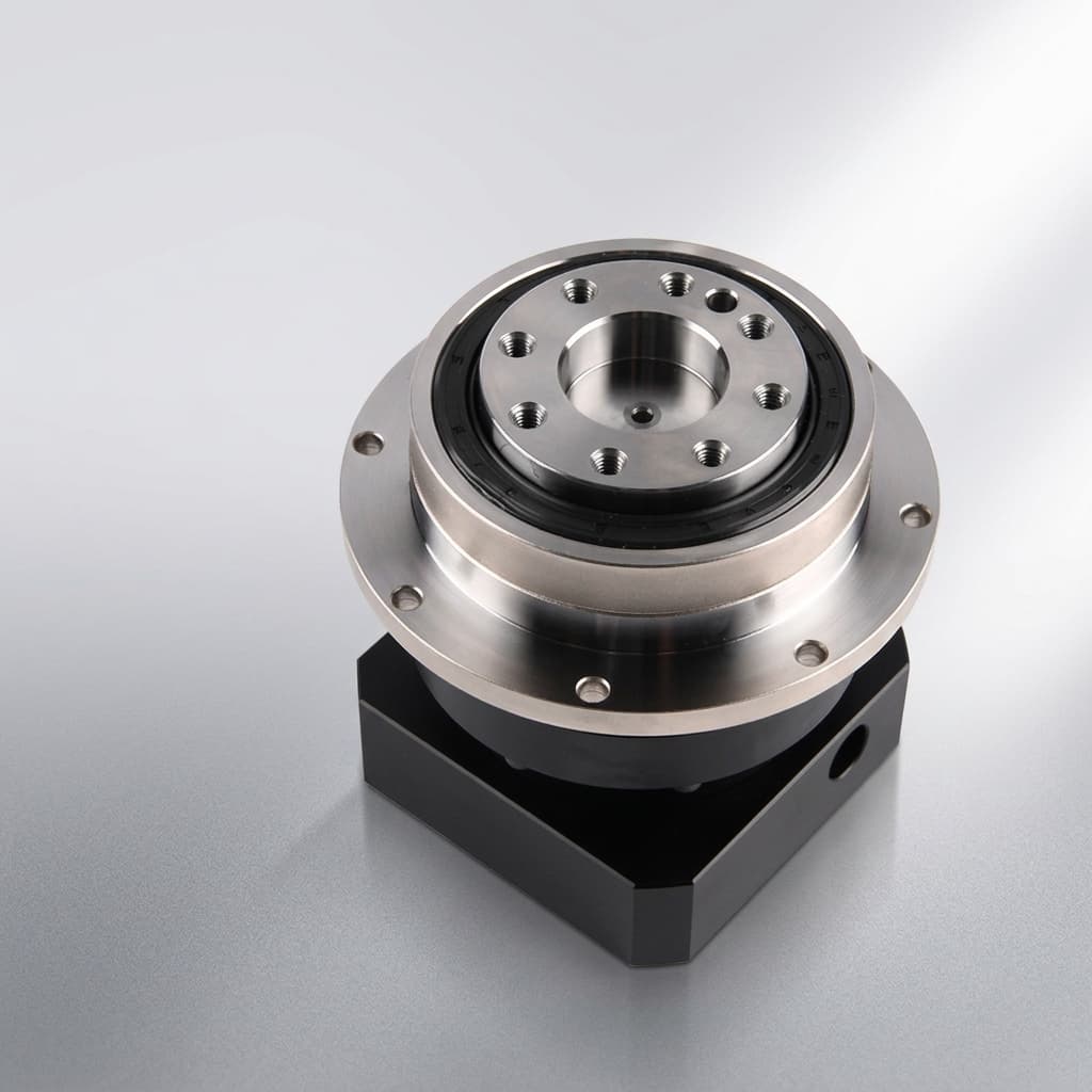
RV Reducer Thermal Rating and Duty Cycle (ED%) Sizing: Preventing Overheating, Grease Breakdown, and Seal Failure in 24/7 Automation
Check RV reducer thermal rating and duty cycle (ED%) with a worked heat-loss example, lubricant limits, and a practical FAT checklist. Prepare your engineering RFQ.
RV Reducer Lost Motion, Hysteresis, and Backlash: Engineering Sizing for Torsional Rigidity, Standards Compliance, and Factory Quality Audits
Understand RV reducer lost motion, backlash and hysteresis. Estimate TCP deflection, compare test methods, and prepare an engineering RFQ with a FAT checklist.