
RV Reducer Mounting Tolerances, Pilot Runout, and Bolt Preload: Preventing High Idling Drag, Noise, and Bearing Spalling
Review RV reducer mounting tolerances, pilot runout and bolt preload with inspection steps, a worked slip calculation and a FAT checklist. Plan your RFQ review.
RV reducer mounting tolerances and bolt preload must come from the selected model's interface drawing and installation instructions. Check pilot size, datum-related runout, mounting-face geometry and the complete fastener specification before releasing the machine flange. A reducer that fits physically can still develop high idling drag, noise or local bearing overload if its housing is distorted during assembly.
For mechanical designers and procurement quality teams, the useful question is not whether a generic flange is “accurate enough.” It is whether the measured interface, tightening process and installed no-load behavior meet an agreed acceptance plan. Mounting errors are one possible cause of these symptoms; lubrication, motor alignment, seals, internal damage and operating conditions must also be investigated. This guide does not assign a warranty-failure percentage to mounting errors.
For baseline gearbox selection, refer to our heavy payload robot reducer selection guide and thermal rating and duty cycle guide. For review of your flange drawings, contact our application engineering team with the model, drawing revision and operating load case.
Engineering and procurement takeaways
- Separate size from geometry: H7 specifies a bore size tolerance zone; it does not establish concentricity, runout, flatness or perpendicularity.
- Approve the torque path: Check whether friction, fitted features or a designed combination transfers torque. Ordinary clearance-hole bolts are not automatically shear keys.
- Specify the complete bolted joint: Bolt class, engagement, bearing surface, coating, lubrication and tightening method belong on the assembly specification.
- Compare like-for-like drag measurements: Record speed, temperature, lubrication, rotation direction and instrument uncertainty before interpreting a change.
- Release against model-specific limits: A low drag change is supporting evidence, not proof that every internal clearance or fatigue requirement is satisfied.
1. Scope, Operational Boundaries, and Content Date
Published and content reviewed: November 9, 2026. Region: Global; language: English. This guide covers mechanical integration planning for two-stage RV-type cycloidal reducers used in industrial robots, welding positioners, turntables and rotary tables. Component sets and enclosed gearheads have different support, sealing and assembly requirements; do not assume instructions transfer between series or manufacturers.
The scope is the interface between the reducer and machine structure: pilot geometry, flange contact, fastener preload, inspection and factory acceptance testing (FAT). Internal gearbox repair, robot functional safety validation and complete joint fatigue design require separate procedures.
Evidence boundary: The linked ISO records identify the scope of fit and geometrical-tolerancing standards; VDI identifies its bolted-joint calculation framework; Nabtesco describes its two-stage mechanism. These public pages do not provide a universal RV mounting tolerance or torque schedule. The inspection workflow and worked arithmetic below are editorial engineering aids, not measured product tests, customer case studies or certification. Obtain the actual model's installation manual, applicable standards and approved drawings before production release. Recheck this guide when those documents or the joint design change.
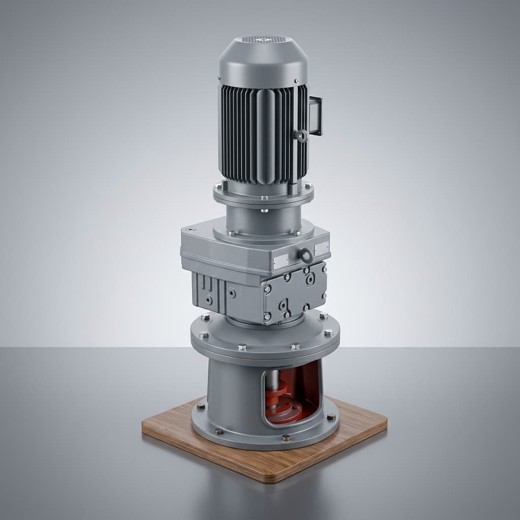
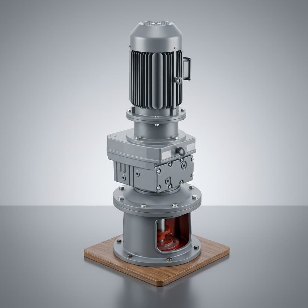
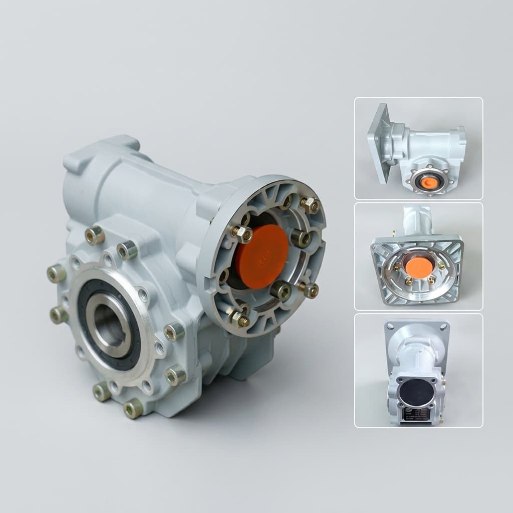
Illustrative assembly image showing a motor, reducer housing and flanged support. It is not a dimensional drawing, a verified internal RV mechanism view or evidence of bolt grade, measured accuracy or a particular serialized product.
2. The Physics of Mounting Distortion: Why Precise Housings Matter
Nabtesco's mechanism overview describes a first-stage gear train driving eccentric crankshafts and a second-stage cycloidal reduction mechanism. Small internal geometry changes can alter load distribution, but the number of crankshafts, clearances and materials depend on the design. Do not infer sub-micron manufacturing tolerances or an internal clearance value from the architecture alone.
2.1 Housing Warping and Pin-Wheel Ovality
Burrs, coating buildup, debris or an uneven support face can prevent full seating. Tightening against these features may bend a flange or distort a housing, redistributing bearing and gear contact loads. The effect depends on support stiffness, bolt location and reducer construction. A measured face deviation alone cannot establish contact stress, remaining clearance or time to spalling; those conclusions need a validated model or inspection evidence.
2.2 Radial Pilot Misalignment and Bearing Overload
An off-axis pilot can misalign the reducer with a motor adapter, coupling or driven table. Depending on the constrained members, this may introduce additional bearing or coupling loads and periodic drag. Check the complete datum chain rather than assuming every assembly error acts directly on internal crankshaft bearings. Motor current can reveal a change, but it also includes motor losses and control effects.
2.3 Frictional Heating in a Bound Assembly
At a defined shaft, drag power is P_loss = T_drag × angular speed, with torque in N·m and speed in rad/s. Increased drag therefore adds heat at the same speed. Temperature also changes grease viscosity, seal friction and joint dimensions, so hot and cold results are not interchangeable. Stop a test for unexpected binding, noise, temperature rise or current according to the approved test plan; do not continue running merely to see whether the gearbox frees up.
3. Geometrical Tolerances & Fit Standards (GD&T)
ISO 286-1 addresses size tolerances and fits. ISO 1101 addresses geometrical specifications. These serve different purposes: an in-size bore can still be off-axis, and an acceptably flat face can still be tilted relative to the required axis.
Fit interpretation, only when H7/h7 is specified on the approved drawing:
H7 bore: lower size deviation is zero.
h7 external pilot: upper size deviation is zero.
H7/h7 is a clearance fit with possible zero minimum clearance,
not a transition fit. Actual limits depend on nominal size.
Neither designation supplies a runout or flatness requirement.
Do not select a pilot fit from reducer frame names alone. Obtain actual diameter limits, thermal conditions, assembly clearance and any coating allowance. A forced fit can introduce load before a bolt is tightened.
The following interface-control table replaces a generic size-based tolerance schedule. Every limit must be filled from the selected model's approved drawing and the machine's accuracy budget.
| Interface characteristic | What to specify | Inspection method | Release evidence |
|---|---|---|---|
| Pilot diameter and fit | Bore and pilot limits at the reference temperature | Bore gauge or internal micrometer and external diameter measurement | Actual sizes, temperature and calculated fit |
| Radial pilot runout | Datum axis, controlled surface and permitted variation | Indicator sweep on a verified spindle or datum-based CMM inspection | Maximum-minus-minimum reading and fixture details |
| Mounting-face flatness | Controlled contact area and flatness limit | Surface mapping or suitable CMM method | Evaluation covering the contact area, not one circular trace |
| Face orientation/runout | Datum, measurement radius and specified geometrical control | Datum-based face sweep or specified CMM evaluation | Reading, radius and datum setup |
| Surface texture | Required texture parameter and evaluation conditions | Profilometer where required | Traceable texture result on the mating area |
| Corner clearance | Housing corner envelope and mating relief | Drawing review plus profile or seating check | Clearance without contact at the corner |
| Bolt pattern and seating | Hole position, spotface, clearance and usable thread depth | Dimensional inspection and approved assembly check | Pattern, seating and depth records |
3.1 Chamfer and Relief Requirements
A pilot-to-face corner must clear the reducer's actual corner radius and any seal or adjacent feature. Specify the mating chamfer or undercut from that envelope; there is no universal 1.5 mm chamfer suitable for every RV size. Verify that the assembly seats on its intended face before tightening. Do not pull an interference or corner clash into place with the mounting bolts, and do not grind a reducer housing to make an unapproved interface fit.
4. Bolted Joint Mechanics (VDI 2230): Preload and Friction Transmission
VDI 2230 Part 1 covers highly stressed joints with one cylindrical bolt. A multi-bolt reducer flange also needs load-distribution and joint-level analysis. A friction screening calculation alone is not a complete VDI assessment: check separation, bolt stress and fatigue, thread stripping, local bearing pressure and external moments.
4.1 Frictional Torque Transmission: A Screening Calculation
For an assumed friction-driven joint that remains closed, a simplified capacity estimate is:
T_slip,screen = mu_interface × F_clamp,residual,total × r_effective
S_slip,screen = T_slip,screen / T_demand
Here mu_interface is a justified lower-bound friction coefficient at the mating faces, not the thread friction coefficient. F_clamp,residual,total is the minimum retained clamp force after tightening scatter, settling, thermal changes and the effect of external loading. The effective friction radius comes from the contact-pressure distribution; it is not automatically the pilot radius or bolt-circle radius. Use N, m and N·m consistently.
Worked hypothetical example, not a reducer rating: Assume 12 bolts retain at least 20 kN clamp force each, the justified interface friction coefficient is 0.12, and the contact model gives an effective radius of 0.080 m. The estimate is 0.12 × 12 × 20,000 × 0.080 = 2,304 N·m. Against an assumed 1,800 N·m demand, the screening ratio is 2,304 / 1,800 = 1.28. If the project requires 1.50, this example does not meet that target. If friction instead falls to 0.08, estimated capacity falls to 1,536 N·m. Those assumed coefficients are sensitivity inputs, not approved values for clean, oiled or painted surfaces.
This example shows why a nominal bolt torque cannot establish slip resistance by itself. Set the required margin through the project design criteria; do not treat 1.50 as a universal VDI requirement. Changing bolt count, diameter or adding keys requires a complete interface redesign and manufacturer agreement.
4.2 Fastener Specifications and Tightening Torque
Use the fastener property class and head style required by the selected installation manual. ISO 4762 identifies a socket-head screw product standard; it does not by itself establish property class 12.9. Neither upgrading nor downgrading the class is automatically acceptable because the female thread, flange and under-head contact can govern joint strength.
| Assembly input | Required specification | Why procurement and QC need it |
|---|---|---|
| Fastener identity | Diameter, pitch, length, head form and property class | Prevents a visually similar substitute |
| Surface condition | Coating, lubricant and approved reuse policy | Controls tightening friction and scatter |
| Torque or tension method | Approved setting, range and sequence | Links assembly action to the qualified joint |
| Clamp-force design | Maximum assembly and minimum retained preload | Checks strength and slip at opposite extremes |
| Female thread | Material, engagement, depth and insert specification | Prevents stripping and bottoming |
| Head bearing surface | Washer or direct-seat arrangement and pressure limit | Controls indentation and settling |
| Tool control | Calibration, working range and recorded result | Makes the assembly process traceable |
Torque control has preload scatter even with a calibrated wrench. Do not interpret a ±5% wrench setting window as ±5% clamp-force accuracy, and do not substitute an impact tool for the qualified tightening process. Where clamp load is critical, agree a validated tension-control or verification method with the joint designer.
5. Visual Guide: Dial-Indicator Runout QC & Cross-Pattern Torquing
The diagram shows indicator contact directions and an illustrative opposing-pair tightening pattern. The percentages are example process stages, not a manufacturer torque instruction. A face sweep measures axial variation about the setup axis; assess flatness separately over the specified area.
Figure 1: Original conceptual inspection and tightening schematic, not a dimensional drawing or test record. (A) Indicator contact on the pilot and mounting face, swept about the datum spindle axis. Face runout does not independently establish flatness. (B) Bolt positions are numbered clockwise; an illustrative opposing-pair order is 1, 7, 4, 10, 2, 8, 5, 11, 3, 9, 6, 12. Use the manufacturer-approved sequence and torque stages.
6. Multi-Material Thread Engagement & Structural Housing Rules
An aluminum or iron mounting structure requires its own thread and bearing-pressure assessment. A high-strength bolt cannot compensate for a weak female thread, a thin wall or an unsupported spotface. Longer engagement also cannot fix a screw that bottoms in a blind hole before the head clamps the flange.
6.1 Thread Engagement Assessment
Do not release a joint solely from a rule such as one bolt diameter in steel or two in aluminum. Required engagement depends on thread geometry and tolerance, bolt preload, parent-material strength in its actual condition, edge distance and load distribution. Specify usable full threads; drill depth and tap depth are not the same as effective engagement. Use an accepted thread-stripping calculation or a validated supplier design, including the insert system when present.
| Parent material | Information required | Joint-design question |
|---|---|---|
| Structural steel | Grade, heat treatment and verified properties | Do thread stripping and head bearing checks meet the maximum preload? |
| Ductile iron | Casting grade, section properties and thread condition | Are local strength and edge distances adequate? |
| Grey cast iron | Grade, porosity acceptance and machining quality | Is a tapped joint suitable for the required cyclic loading? |
| Cast aluminum | Alloy, temper and casting quality | Is a qualified insert or alternative joint needed? |
| Wrought 6061 aluminum | Temper, thickness and service temperature | Are engagement and bearing pressure acceptable? |
| Wrought 7075 aluminum | Temper, environment and surface treatment | Are strength, corrosion and maintenance requirements compatible? |
6.2 Surface Pressure and Preload Retention
Under-head indentation, interface settling and coatings can reduce retained clamp force. Estimate bearing pressure from the actual contact area and load; do not assume a fixed percentage loss in the first day. A washer changes contact area, grip length and friction. Where specified, use the required dimensions, hardness and strength class, and confirm compatibility with the bolt and spotface. A generic washer standard or an “HV 300” label alone does not approve a class 12.9 joint. Thread inserts protect threads only when the insert, parent wall and installation have been qualified.
6.3 Thread Locker and Lubrication Changes
Wet anaerobic adhesive, oil, plating and anti-seize can change torque-to-preload behavior. There is no generally valid 10–15% or 30–40% torque correction. Use a torque specification validated for the exact fastener, coating and chemical condition, including curing and reuse rules. Keep face-contact condition separate from thread lubrication: a lubricant approved on a screw may be unacceptable on a friction-driving flange.
If your supplier's torque schedule omits these conditions, request an engineering review of the mounting specification before releasing an assembly instruction. Include both the fastener data and parent-material details so the review can address the whole joint.
7. Dowel Pins and Shear Protection Under Emergency-Stop Torques
Determine emergency-stop torque from the actual motion, inertia, braking strategy and load path. A gearbox's published momentary torque capacity does not establish the torque transmitted through a mounting interface in a collision or stop. Robot functional safety and reducer mounting qualification are separate engineering tasks.
Dowels may locate parts, transmit shear or serve both roles if designed accordingly. Clearance and stiffness determine when they engage; friction and pin capacities cannot simply be added without evaluating displacement and load sharing. Check pin shear, bearing pressure, edge breakout, fatigue and flange strength. An alignment dowel is not automatically a crash containment feature.
7.1 Precision Dowel Fit and Installation
Use the drawing's pin type, fit, position and installation method. A hole marked H7 does not fully define the pin fit without the pin tolerance. Do not drill or ream a supplied gearbox flange unless its manufacturer approves the operation. Match machining, where authorized, must preserve interchangeability and traceability. Never force a locating pin to correct a misaligned assembly.
8. Quality Control & FAT: The No-Load Drag Verification Protocol
A controlled before-and-after drag comparison helps detect an assembly-induced change. It cannot by itself prove absence of housing stress, certify bearing life or diagnose the cause of spalling. Agree absolute torque or current limits and change limits before testing, using manufacturer requirements and process capability.
8.1 Step-by-Step Assembly & FAT Procedure
- Prepare and identify. Record reducer serial number, drawing revision, adapter identity, fastener lot and lubricant condition. Secure the mechanism against unintended motion and support the load before any loosening. Clean permitted mating surfaces with a compatible cleaner, protecting seals and lubricant from solvent ingress.
- Inspect geometry. Verify pilot sizes and seating. Sweep the pilot about the specified datum axis and record maximum minus minimum indicator reading as TIR. Record fixture accuracy, measurement radius, temperature and instrument resolution. Map face flatness separately. Compare each result with its drawing limit, rather than inferring flatness from face runout. Correct only approved features and re-inspect after any machining.
- Establish a supported baseline. Use an approved fixture so an unbolted component set is not run without required support, lubrication or retention. Measure running drag with a suitable continuous-reading torque instrument or transducer at a defined low speed, direction and temperature. Keep breakaway torque separate. A click-type assembly wrench is not a running-torque measuring instrument.
- Tighten under the qualified process. Check usable thread depth and insert every specified fastener without forcing. Use the approved stages and opposing-pair sequence; Figure 1 is illustrative. Record tool settings and results. Perform a final verification pass only as instructed, since repeatedly turning bolts can alter preload or disturb curing thread locker.
- Repeat under matching conditions. Measure installed drag over the same motion range with the same instrumentation, lubrication, speed, direction and temperature. Record the full variation, not only an average. Motor current is a proxy only after the motor torque constant, control mode and other losses have been accounted for.
- Classify and document. Compare absolute drag and the measured change with approved limits and measurement uncertainty. Hold the assembly for unexplained binding, periodic notching or excessive noise. After securing the load, investigate seating, pilot fit, bolt length, coupling alignment and internal condition with the supplier. Do not stone or dismantle precision gearbox parts as a default response.
Delta_T_idle_percent = 100 × (T_installed - T_baseline) / T_baseline
Use only when the baseline is positive and well above measurement uncertainty.
Near zero baseline: compare absolute torque changes instead.
Release: all geometry, fastener and FAT requirements meet approved limits.
Hold: any requirement fails, is unknown, or shows an unexplained change.
Hypothetical measurement example: At the same speed and temperature, a baseline of 0.80 N·m and an installed reading of 0.92 N·m give an absolute increase of 0.12 N·m and a relative increase of 15%. These are arithmetic inputs, not product test results. Whether that change is acceptable depends on instrument uncertainty, normal variation and the model's agreed limit. A universal “15% passes, 30% rejects” rule would conceal those dependencies.
9. Procurement and Assembly Verification Checklist
Attach this checklist to the RFQ and inspection traveler so supplier, machinist and assembler work to the same requirements:
- Controlled documents: Model, serial number, interface drawing and installation-manual revisions are recorded.
- Pilot fit: Both mating sizes meet the specified limits, reference temperature and assembly-clearance requirement.
- Datum inspection: Radial runout and face controls include the correct datum, measurement radius and recorded results.
- Full seating: Flatness, surface condition and corner relief meet the drawing; bolts are not used to overcome a clash.
- Fastener identity: Size, length, property class, coating and lot match the approved bill of materials.
- Female thread and head support: Usable engagement, blind-hole clearance, insert and washer arrangements are approved.
- Friction conditions: Thread lubricant or adhesive and mating-face condition match the qualified process.
- Tool and sequence: Calibration, working range, torque or tension settings and tightening stages are documented.
- Torque path: Retained clamp force, friction assumptions, stop load and any pin/key contribution have been reviewed.
- No-load comparison: Baseline and installed results include speed, temperature, direction, uncertainty and acceptance limits.
- Release decision: Deviations have an agreed disposition; unresolved requirements prevent production acceptance.
10. Frequently Asked Questions (FAQ)
Why does the input shaft feel stiff or notched after tightening the mounting bolts?
Possible causes include incomplete seating, interference at the pilot or corner, flange deformation, a bottomed screw, coupling misalignment or internal damage. Stop the test and secure the mechanism before changing fasteners. If drag decreases after controlled loosening, that supports an assembly-related load change; it does not prove the gearbox is defect-free or that the mounting face alone caused it. Preserve the inspection results for supplier review.
Can I use split lock washers on RV reducer mounting bolts?
Use only the washer or direct-seat arrangement approved for the joint. Do not add split washers, disc springs or other locking devices as substitutes for a controlled preload process. Their effect on seating, friction and retained clamp load needs validation. Even a hardened flat washer must have the specified dimensions and strength compatibility; hardness alone is not enough.
How does thermal expansion affect a bolted joint in an aluminum robot arm?
Different thermal expansion of the housing and bolt can change clamp load during heating and cooling. The direction and magnitude depend on grip length, stiffness, temperature distribution and local yielding or settling. Evaluate the actual thermal cycle and manufacturer temperature limits. Deeper threads or a washer alone do not resolve the problem. Any post-cycle inspection or retightening must follow the approved procedure, especially with cured adhesive.
Is anti-seize paste acceptable on mounting bolts?
Only where the installation specification allows that exact product and provides a validated tightening process. Do not apply a fixed percentage torque reduction from an unrelated table. Prevent contamination of friction-driving mating faces and document any permitted lubricant change with the supplier before assembly.
What is the maximum allowable radial pilot runout for a welding turntable?
There is no single value for all turntables. Allocate runout from the selected reducer drawing, bearing arrangement, table geometry and welding accuracy requirement. State the datum and measurement location: pilot TIR and weld-path accuracy at a larger radius are different requirements. For a purely eccentric, round feature, TIR is twice the radial center offset; form error or fixture error makes that shortcut unreliable.
Why does the catalog show dowel holes if bolts transmit torque by friction?
The holes may serve location or an explicitly engineered shear function. Confirm the purpose with the manufacturer. A clearance-fit locating pin may engage only after movement, while a fitted shear feature has different installation and load-sharing requirements. Do not credit dowels with emergency-stop capacity without checking the complete pin, hole and flange load path.
11. Sources and Next Engineering Step
Public source records checked November 9, 2026. The scope of each reference is stated below; access to an abstract or overview does not verify a complete standard calculation or model-specific installation limit.
- ISO 286-1:2010: Basis of tolerances, deviations and fits. Supports the distinction between size tolerance classes and other geometrical controls; obtain the applicable size-dependent limits for your drawing.
- ISO 1101:2017: Geometrical tolerancing: form, orientation, location and run-out. Identifies the specification framework; it does not prescribe an RV reducer's numerical mounting limits.
- VDI 2230 Part 1, 2015-11: Systematic calculation of highly stressed bolted joints — Joints with one cylindrical bolt. Supports evaluating tightening scatter and the distinction between maximum assembly preload and minimum retained clamp force. A multi-bolt flange requires additional joint-level analysis.
- Nabtesco Motion Control: Cycloidal gear technology and RV mechanism overview. Supports the two-stage mechanism description. This page is not an installation tolerance, bolt torque or drag-acceptance table.
Preparing a robot joint or positioner RFQ? Send the reducer model, flange drawing revision, parent material, fastener specification, motion profile and peak stop-load case to our application engineering team. Request confirmation of model-specific interface limits, assembly conditions and FAT acceptance criteria before approving production tooling.
Author

Categories
More Posts
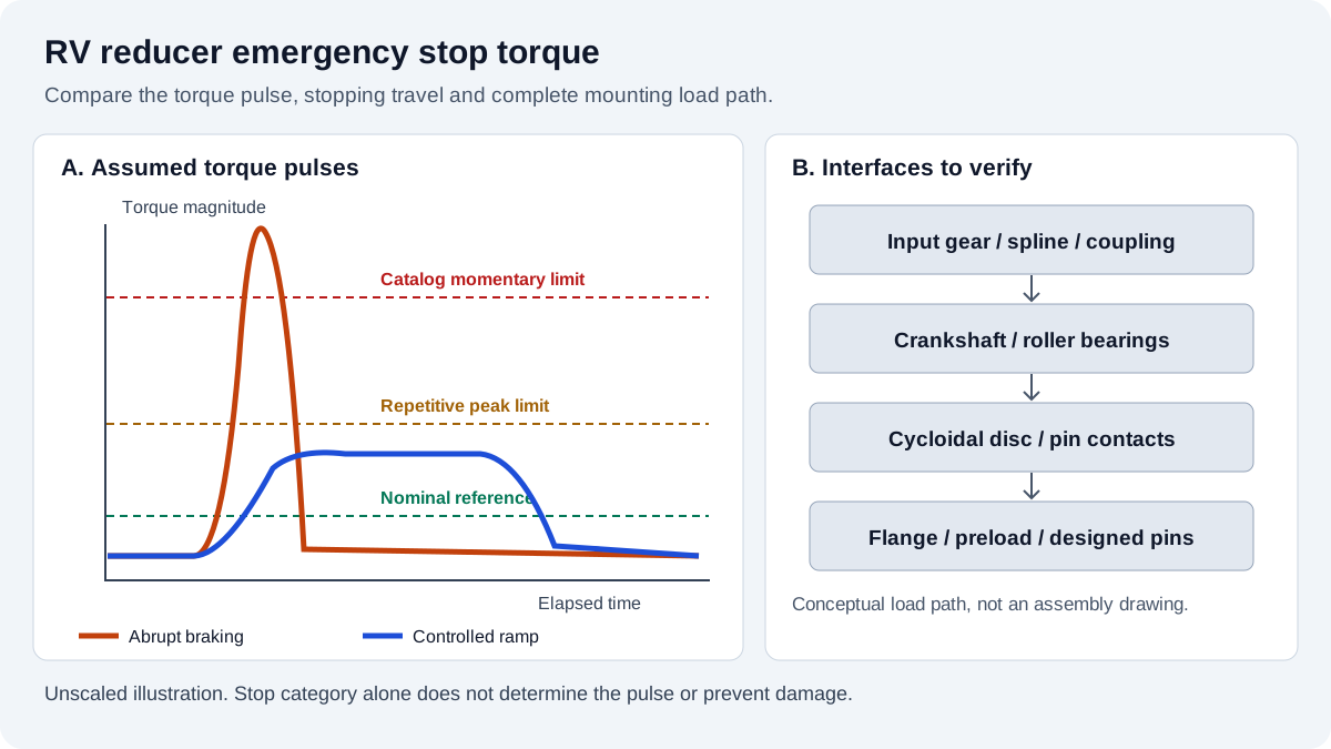
RV Reducer Emergency Stop Torque Rating, Dynamic Braking, and Peak Shock Margin: Sizing to Prevent Pin Shearing, Tooth Indentation, and Fastener Failure
Check RV reducer emergency stop torque, dynamic braking, and peak shock margin with a worked example and supplier checklist. Prepare your engineering RFQ.
RV Reducer Thermal Rating and Duty Cycle (ED%) Sizing: Preventing Overheating, Grease Breakdown, and Seal Failure in 24/7 Automation
Check RV reducer thermal rating and duty cycle (ED%) with a worked heat-loss example, lubricant limits, and a practical FAT checklist. Prepare your engineering RFQ.
RV Reducer Lost Motion, Hysteresis, and Backlash: Engineering Sizing for Torsional Rigidity, Standards Compliance, and Factory Quality Audits
Understand RV reducer lost motion, backlash and hysteresis. Estimate TCP deflection, compare test methods, and prepare an engineering RFQ with a FAT checklist.