
Compact Cycloidal Gearbox for Humanoid Ankle Joint
Estimate torque, speed and fit. Prepare requirements for a supplier review.
Size your ankle gearbox ↓Ankle sizing tool
Single-support pitch estimate; gait factors and efficiency are assumptions. Contact stress, backdrive drag and fatigue life are unknown.
View checks and next stepRequired · 20–150 kg. Total biped robot mass including battery and payload.
Required · 60–300 mm. Effective moment arm from ankle pitch axis to metatarsal ground contact.
Gait, motor and envelope assumptions (editable)
Required · 1–5 ×. Assumed vertical ground-force / body-weight ratio in single support; replace with gait data.
Required · 50–1200 deg/s. Required joint velocity during push-off and rapid swing recovery.
Required · 11–100 :1. Proposed ratio; confirm availability and speed limits for the exact gearbox.
Required · 500–30000 rpm. Loaded motor speed at nominal bus voltage.
Required · 50–100 %. Scenario assumption, not a measured efficiency map; excludes motor and inverter losses.
Required · 1.5–6 × push-off. Assumed impact torque / push-off torque ratio; not a GRF multiplier or measured pulse duration.
Required · 0.01–6 ×. Illustrative duty assumption; replace with RMS of a complete measured gait torque trace, including impacts.
Required · 10–500 Nm. Overturning moment from uneven terrain and lateral roll maneuvers.
Required · 15–100 mm. Maximum axial thickness allocated to the reducer inside the ankle.
Required · 40–160 mm. Maximum radial envelope constrained by shank/ankle link contours.
Required · 0–50 mm. Through-hole clearance for 6-axis F/T sensor and tactile bus harness.
Candidate datasheet (optional)
Blank means unknown. Numeric matches still require supplier confirmation for the exact duty and combined loads.
Optional · 1–1000 Nm. Use verified data for the exact candidate and operating conditions.
Optional · 1–2000 Nm. Use verified data for the exact candidate and operating conditions.
Optional · 1–5000 Nm. Use a supplier-approved repeated-impact rating for your pulse and cycle count; leave blank if only emergency overload is known.
Optional · 1–2000 Nm. Use verified data for the exact candidate and operating conditions.
Optional · 10–200 mm. Use verified data for the exact candidate and operating conditions.
Optional · 30–200 mm. Use verified data for the exact candidate and operating conditions.
Optional · 0–80 mm. Use verified data for the exact candidate and operating conditions.
Try 3 illustrative scenarios
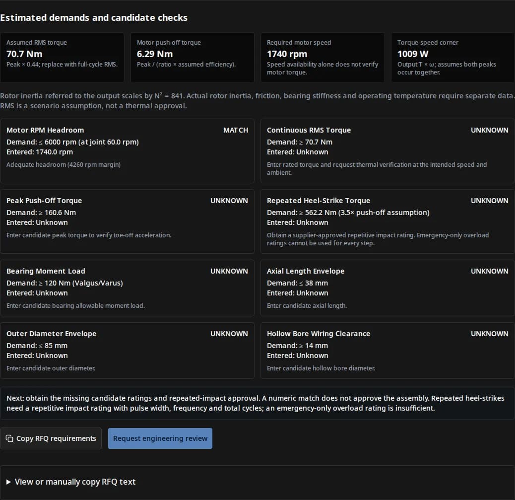
Estimated demands and candidate checks
Assumed RMS torque
70.7 Nm
Peak × 0.44; replace with full-cycle RMS.
Motor push-off torque
6.29 Nm
Peak / (ratio × assumed efficiency).
Required motor speed
1740 rpm
Speed availability alone does not verify motor torque.
Torque-speed corner
1009 W
Output T × ω; assumes both peaks occur together.
Rotor inertia referred to the output scales by N² = 841. Actual rotor inertia, friction, bearing stiffness and operating temperature require separate data. RMS is a scenario assumption, not a thermal approval.
Demand: ≤ 6000 rpm (at joint 60.0 rpm)
Entered: 1740.0 rpm
Adequate headroom (4260 rpm margin)
Demand: ≥ 70.7 Nm
Entered: Unknown
Enter rated torque and request thermal verification at the intended speed and ambient.
Demand: ≥ 160.6 Nm
Entered: Unknown
Enter candidate peak torque to verify toe-off acceleration.
Demand: ≥ 562.2 Nm (3.5× push-off assumption)
Entered: Unknown
Obtain a supplier-approved repetitive impact rating. Emergency-only overload ratings cannot be used for every step.
Demand: ≥ 120 Nm (Valgus/Varus)
Entered: Unknown
Enter candidate bearing allowable moment load.
Demand: ≤ 38 mm
Entered: Unknown
Enter candidate axial length.
Demand: ≤ 85 mm
Entered: Unknown
Enter candidate outer diameter.
Demand: ≥ 14 mm
Entered: Unknown
Enter candidate hollow bore diameter.
Next: obtain the missing candidate ratings and repeated-impact approval. A numeric match does not approve the assembly. Repeated heel-strikes need a repetitive impact rating with pulse width, frequency and total cycles; an emergency-only overload rating is insufficient.
View or manually copy RFQ text
Use Ctrl/Cmd+C or your device’s text selection, then paste into the contact form.
Published · Reviewed by RV Reducer. Source and software review; no physical ankle testing is claimed. Next review: May 2027, or sooner if the method or sources change.
What to decide before shortlisting a gearbox
| Decision | Basis | Next action |
|---|---|---|
| Separate repeated impact from emergency overload | Manufacturer rating definitions distinguish normal repeated peaks and emergency events [torque-ratings]. | Obtain approval for the heel-strike pulse and total cycle count. |
| Treat cycloidal QDD as a candidate architecture | A published 10:1 research design demonstrates a specific implementation, with nonlinear dynamics [cqdd]. | Compare prototypes under the same load, speed and control requirements. |
| Verify the whole bearing installation | Crossed rollers can support multiple load directions [bearing]; assembly capacity remains unknown. | Review combined loads, fit, mounting bolts and permissible tilt. |
| Keep assumed and measured values separate | The calculator is a reproducible scalar model, not measured gait data. | Replace scenario factors with a full torque-speed trace before qualification. |
Reproduce the estimate and see its limits
This page’s screening model uses single support: one foot carries the specified vertical ground force. The horizontal lever arm is measured from the pitch axis to its line of action. It ignores horizontal ground force, link inertia and coupling. The default multipliers are illustrative assumptions.
| Output | Equation | Boundary |
|---|---|---|
| Push-off torque (Nm) | T = m (kg) × 9.80665 (m/s²) × force factor × lever arm (mm) / 1000 | Vertical-force moment only; use inverse dynamics for full demands. |
| Assumed RMS torque (Nm) | T_RMS = T × user RMS factor (default 0.44) | Replace with sqrt(Σ Tᵢ² Δtᵢ / Σ Δtᵢ), including short impact pulses. |
| Repeated impact demand (Nm) | T_impact = T × user impact multiplier | Independent assumed load case; no pulse duration or life is predicted. |
| Motor speed (rpm) | n_motor = joint speed (deg/s) / 6 × ratio N | Motor loaded speed only; gearbox max/average input speed still need checking. |
| Motor torque and output power | T_motor = T / (N × efficiency); P_corner = T × speed × π / 180 | Assumes constant forward efficiency and coincident torque/speed peaks. |
| Output-referred rotor inertia | J_output = J_motor × N² | Reports N² only; no rotor inertia or backdrive friction is inferred. |
A true duty cycle must include stance, swing, repeated impacts and rest. Gearbox fatigue-equivalent torque follows the selected manufacturer’s method and may differ from motor thermal RMS. The table is a transparent model definition, not a claimed test standard.
Three reproducible demand scenarios
Illustrations only; not measured walking or running cases and not product recommendations. Each preset resets candidate ratings. All retain the default 0.44 RMS factor. Use the tool above to change any assumption.
| Case / inputs | Estimated output demands (Nm) | Required motor speed | Interpretation |
|---|---|---|---|
| 50 kg scenario: 130 mm arm, force factor 2.4, impact factor 4.0, ratio 21:1 | 153.0 push-off / 67.3 assumed RMS / 611.9 repeated impact | 1680 rpm at 480 deg/s | Candidate unknown; request ratings and duty validation. |
| 65 kg scenario: 140 mm arm, force factor 1.8, impact factor 3.5, ratio 29:1 | 160.6 push-off / 70.7 assumed RMS / 562.2 repeated impact | 1740 rpm at 360 deg/s | Candidate unknown; request ratings and duty validation. |
| 90 kg scenario: 160 mm arm, force factor 2.0, impact factor 3.8, ratio 39:1 | 282.4 push-off / 124.3 assumed RMS / 1073.2 repeated impact | 1950 rpm at 300 deg/s | Candidate unknown; request ratings and duty validation. |
In the default 65 kg case, the assumed repeated impact is approximately 562.2 Nm. A candidate with a 425 Nm emergency-only limit has neither a matching numeric capacity nor evidence for repetitive gait. Lowering a multiplier merely to obtain a match does not establish a valid load case.
Compare ankle layouts before choosing a transmission
| Candidate | Question to resolve | Evidence to request |
|---|---|---|
| Direct ankle cycloidal | Can the full distal package meet torque, speed, friction and inertia targets? | Full actuator mass/CAD, torque ripple map, repeated-impact tests and thermal curve. |
| Strain-wave | Can the selected unit meet repetitive loads, compliance and lifetime requirements? | Exact model duty calculation, stiffness/lost-motion curves and repeated peak limits. |
| Planetary / low-ratio QDD | Can motor current, cooling and gearbox envelope meet the same demand? | Motor torque-speed curve at bus voltage, efficiency map and endurance evidence. |
| Remote parallel pitch-roll | Does proximal placement justify linkage complexity and workspace variation? | Jacobian, singularity margins, joint forces, travel and harness routing. |
This is a decision framework, not a measured comparison. Coupled pitch-roll linkages require a workspace-dependent transmission model; this tool’s scalar screen does not size those linkages.
Prepare an ankle engineering RFQCompare wearable joint requirementsExplore transmission comparisonWhat is known and what remains unverified
| Item | Known here | Unverified / required next |
|---|---|---|
| Force, torque and speed conversion | Published page equations; user-selected scenario assumptions. | Measured GRF, horizontal forces, inertia and complete gait trace. |
| Cycloidal research | Zhu et al. describe a particular 10:1 actuator [cqdd]. | Transfer to a commercial ankle or another ratio, material or scale. |
| Bearing principle | Crossed rollers can receive radial, axial and moment loads [bearing]. | Actual combined-load limit, mounting stiffness and angular deflection. |
| Contact stress / backdrive / lifetime | N/A: required geometry, material and measurements are not supplied. | Supplier calculation and assembly-specific bench/endurance tests. |
| Commercial candidate | No verified ankle model datasheet is supplied here. | Revision-controlled dimensions, torque ratings, price, stock and lead time. |
General standards or research prototypes do not certify an unidentified product. No shock percentage, fatigue life, thermal result or commercial availability is asserted for an ankle gearbox on this page.
Mitigate misuse, cost and integration risks
| Risk | Consequence | Minimum mitigation |
|---|---|---|
| Emergency rating used for every step | Cycle-dependent damage can be missed by a scalar torque comparison. | Require supplier confirmation of waveform, repetition and lifetime; measure transmitted loads. |
| Gearbox-only package treated as complete ankle | Motor, encoder, bearing support or harness may exceed the envelope. | Check full assembly CAD through travel; include connector bend radius and bolt access. |
| Assumed efficiency or RMS treated as validation | Motor current, heat and battery demand may be underestimated. | Use measured maps and gait traces; instrument repeated-duty thermal tests at worst ambient. |
| Custom thin housing / bore / preload | Tooling, iteration, yield and inspection can change the quote. | Separate NRE, sample, production, testing and spares costs; agree acceptance criteria. |
| Parallel linkage sized as direct pitch drive | Changing leverage or singularities can exceed individual actuator loads. | Calculate the workspace Jacobian; compare remote/direct alternatives before procurement. |
Turn a numerical screen into a qualification plan
- Measure or simulate the complete torque-speed history, including terrain, payload, braking and impact pulses. Record uncertainty and sign conventions.
- Obtain a revision-controlled candidate datasheet. Confirm repeated torque, impact cycle allowance, input speed, combined bearing loads and full actuator dimensions.
- Bench-test starting/running backdrive torque, bidirectional stiffness and lost motion at relevant temperatures, with motor control state specified.
- Validate electrical, thermal, housing and harness behavior on a representative assembly. Inspect after a staged repetitive-impact endurance test before full robot deployment.
If data is missing, copy the requirements from the tool and request a manual engineering review. Compare samples under the same protocol before committing to tooling or production quantities.
Primary evidence and source boundaries
Sources checked 1 November 2026. Edition dates identify the cited work; public research and manufacturer guidance are used only within the scopes below. No certification of this page’s calculator is implied.
- Zhu, Tanaka, Rafeedi & Hong — Cycloidal Quasi-Direct Drive Actuator Designs with Learning-based Torque Estimation for Legged Robotics
arXiv:2410.16591v2, revised 20 March 2025; sections II-B, III and V
Research example of a 10:1 cycloidal actuator, with prototype-specific dynamics and testing. It does not validate a commercial humanoid ankle gearbox or a universal ratio, impact rating or backdrive value.
- Harmonic Drive LLC — SHF/SHG component sets and housed units catalog
Technical Terms, Strength & Life, printed page 12; architecture-specific manufacturer guidance
Distinguishes rated, repeated peak and momentary peak torque. Its emergency momentary limits are not for normal repetitive operating cycles; its numeric ratings cannot be transferred to a cycloidal unit.
- THK — Cross-Roller Ring: structure and features
Manufacturer product information; accessed 1 November 2026
Crossed rollers can carry radial, axial and moment loads in one bearing. This general capability does not establish the capacity or stiffness of an unspecified ankle assembly.
Ankle gearbox engineering FAQ
Loads and method
What does the ankle sizing tool calculate?
A preliminary single-support pitch torque from robot mass, vertical force factor and horizontal contact lever arm. It also calculates an assumed RMS torque, repeated-impact demand, motor speed and gearbox envelope checks. Full inverse dynamics and validation remain necessary.
Is the default 0.44 RMS factor measured gait data?
No. It is an editable illustration. Calculate actual RMS from the complete torque trace, including impact pulses, stance and swing: square each torque sample, average over time, then take the square root. Motor thermal RMS and gearbox fatigue-equivalent torque can require different methods.
Does a momentary overload rating cover every heel-strike?
Only use a rating that the supplier explicitly approves for the intended repetitive pulse and lifetime. Emergency-only collision or stop limits cannot be treated as a rating for each step. Leave the repeated-impact field blank until the supplier confirms it.
Why is the force multiplier different from the impact multiplier?
The force multiplier scales body weight to estimate push-off ground force. The impact multiplier then scales estimated push-off torque to a separate assumed impact torque. It is not a second measured ground-force multiplier; avoid double-counting an impact already included in your load trace.
Architecture and integration
Is a cycloidal gearbox always the best ankle transmission?
Selection depends on the load trace, package, motor and control requirements. Compare a cycloidal unit with strain-wave, planetary/QDD or remote actuation candidates using the same duty and test conditions. A transmission name alone does not establish impact endurance or compliance.
Can this tool evaluate a parallel pitch-roll ankle?
The scalar pitch screen cannot transform coupled parallel-linkage loads. Derive each actuator force or torque using the linkage Jacobian across the workspace, account for singularities and evaluate both channels. The input lever arm must not be substituted for a varying linkage ratio.
Does a cross-roller bearing remove the need for structural checks?
No. Request combined radial/axial/moment capacity, allowable tilt, housing tolerances and bolt loads for the exact assembly. A standalone moment rating is only a preliminary comparison; integration may still require external support.
Can reduction ratio predict backdrive torque?
No. Ratio determines kinematic torque and speed relationships, while friction also depends on preload, seals, lubricant, temperature and manufacturing. Measure starting and running backdrive torque on the assembled actuator in both directions.
Qualification and purchasing
Does a numeric match mean the actuator is approved?
It means only that the entered scalar limits match the chosen assumptions. It does not verify motor current, voltage, gearbox input-speed limits, control stability, combined bearing loads, fatigue life or operating temperature.
What does compact mean for the complete ankle?
The tool compares reducer-only diameter, axial length and bore. Add the motor, encoder, output support, seals, fasteners and connector bend radii, then check travel and collisions in full assembly CAD.
What must be included in an ankle gearbox RFQ?
Include torque-speed time histories, repetitive impact pulse width/frequency/total cycles, payload, terrain, ambient temperature, allowable deflection, mass and envelope, harness clearance, quantity, delivery location and required qualification evidence.
Are model prices, lead times and production ratings confirmed here?
No verified commercial ankle model datasheet, price or delivery commitment is supplied on this page. Request an identified drawing revision, test report, quotation and sample validation plan before choosing a production unit.
Request an ankle transmission review
Send the tool’s requirements with your torque-speed trace, impact pulse/cycle target, full CAD envelope, ambient conditions, quantity and delivery location. Ask for a candidate drawing, written duty assessment and sample test plan.
Inquiry Email
Include target torque/speed, quantity, and delivery location.