
Compact Cycloidal Gearbox for Exoskeleton Joint: Sizing & RFQ
Calculate torque and speed, check a supplier candidate and prepare an RFQ. Use the guide to plan qualification.
Use the joint sizing calculator ↓Joint sizing calculator
Torque, speed and shock screening. Fixed example until JavaScript is ready.
Required; measured or estimated assistance peak. Range 0.1–1000.
Required; must not exceed peak torque. Range 0–1000.
Required; maximum output angular speed. Range 0.1–1000.
Required; reserve motor, bearing and cuff space separately. Range 1–300.
Ratio, motor & assumptions — 29:1, 90% efficiency
Required; proposed ratio, not an optimized recommendation. Range 1–200.
Required; use loaded speed from the motor torque-speed curve. Range 1–30000.
Required; illustrative assumption; replace with measured data. Range 1–100.
Required; sensitivity assumption, not a gait or safety standard. Range 1–10.
Examples are hypothetical requirements, not patient prescriptions or verified product ratings. All eight requirement fields are required; candidate fields may stay empty.
Check a supplier candidate (optional)
Use ratings for the proposed ratio and operating conditions. Blank means unknown; all entered limits must be met. Torque duration, input-speed rating and duty cycle still need review.
Optional; use the rating for the proposed ratio from a supplier datasheet. Range 0.1–10000.
Optional; use the rating for the proposed ratio from a supplier datasheet. Range 0.1–10000.
Optional; use the rating for the proposed ratio from a supplier datasheet. Range 0.1–10000.
Optional; use the rating for the proposed ratio from a supplier datasheet. Range 1–1000.
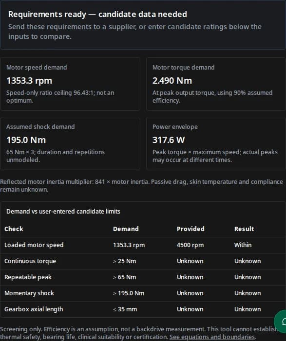
Requirements ready — candidate data needed
Send these requirements to a supplier, or enter candidate ratings below the inputs to compare.
Motor speed demand
1353.3 rpm
Speed-only ratio ceiling 96.43:1; not an optimum.
Motor torque demand
2.490 Nm
At peak output torque, using 90% assumed efficiency.
Assumed shock demand
195.0 Nm
65 Nm × 3; duration and repetitions unmodeled.
Power envelope
317.6 W
Peak torque × maximum speed; actual peaks may occur at different times.
Reflected motor inertia multiplier: 841 × motor inertia. Passive drag, skin temperature and compliance remain unknown.
| Check | Demand | Provided | Result |
|---|---|---|---|
| Loaded motor speed | 1353.3 rpm | 4500 rpm | Within |
| Continuous torque | ≥ 25 Nm | Unknown | Unknown |
| Repeatable peak | ≥ 65 Nm | Unknown | Unknown |
| Momentary shock | ≥ 195.0 Nm | Unknown | Unknown |
| Gearbox axial length | ≤ 35 mm | Unknown | Unknown |
Screening only. Efficiency is an assumption, not a backdrive measurement. This tool cannot establish thermal safety, bearing life, clinical suitability or certification. See equations and boundaries.
Review or manually copy RFQ text
Published · Reviewed by RV Reducer. Engineering methods and source review; no physical wearable testing is claimed. Next review: May 2027, or sooner if sources or models change.
Decision summary: a candidate worth testing, not an automatic fit
Compact cycloidal reducers are a candidate when a wearable joint needs torque multiplication within a tight envelope. The decision must include passive motion and system qualification. The recommendations below are engineering interpretations; calculations and published research have separate limits.
| Decision | Reason | Evidence / next action |
|---|---|---|
| Screen continuous, peak and shock demands separately | An overload rating cannot substitute for a continuous-duty rating. | Use the reproducible equations and request duty-cycle ratings. |
| Validate passive drag before selecting a ratio | Inertia and friction can resist unpowered motion; ratio alone cannot predict transparency. | Research reports nonlinear dynamics; test the complete actuator. |
| Budget the complete actuator stack | A thin reducer does not include every motor, bearing or cuff dimension. | Check the complete CAD section and wearer clearance. |
| Separate component screening from human-contact approval | Thermal risk depends on the real interface and intended use. | Use the hot-surface assessment scope and a system test plan. |
Method: equations, defaults and what they cannot establish
The calculator applies rigid-transmission kinematics and a constant forward-efficiency assumption. Defaults (65 Nm peak, 25 Nm RMS, 280 deg/s, 29:1, 90% efficiency, 3× shock) are an illustrative starting point. No body-mass-to-torque model or medical prescription is implied.
| Output | Equation and units | Boundary |
|---|---|---|
| Motor speed demand | n_motor = (speed_deg/s / 6) × N, in rpm | Use the available speed at the required motor torque, not unloaded motor speed. |
| Speed-only ratio upper bound | N_max = n_available / (speed_deg/s / 6) | A ceiling from speed alone; not the optimal ratio. Verify gearbox input-speed rating separately. |
| Motor torque demand | T_motor = T_peak / (N × eta), in Nm | No acceleration, motor inertia or control reserve included. Efficiency varies with operation. |
| Power envelope | P = T_peak × speed_deg/s × pi / 180, in W | A simultaneous peak envelope. Actual torque and speed peaks may not coincide. Not average heat or bus current. |
| Assumed shock demand | T_shock = T_peak × K_shock, in Nm | A chosen sensitivity multiplier, not a standard-derived heel-strike load. Duration and cycles unmodeled. |
| Reflected rotor inertia term | J_ref,motor = J_motor × N², in kg·m² | Tool shows N² only because motor inertia is unknown. Gear inertia and friction remain additional terms. |
RMS torque must come from a time history: T_rms = sqrt(sum(T_i² × dt_i) / sum(dt_i)). It is a load-screening measure; it does not predict gearbox or skin temperature. Candidate checks compare unrounded numbers, accept equality and leave missing values unknown. Screening bounds are disclosed at each input.
Packaging: reserve space beyond the pancake gearbox
Evaluate radial diameter and full actuator mass alongside axial depth. Moving mass farther from a joint changes its rotational inertia. Check the cuff and anatomical alignment through the entire intended range of motion, including clothing and fitting tolerances. A hollow bore also needs cable bend-radius, twist and service-loop checks.
Alternatives: compare assemblies at the same duty cycle
This is a qualitative selection framework, not a measured ranking of suppliers. Obtain comparable mass, envelope, torque-speed curves, passive drag and endurance data for each proposed assembly.
| Architecture | Reason to investigate | Tradeoff / test before selection |
|---|---|---|
| Compact cycloidal | Compact torque multiplication; published low-ratio research exists. | Characterize torque ripple, backlash, bearings and passive drag on the actual build. |
| Strain wave | Investigate when ratio, stiffness and packaging match the joint needs. | Use model-specific repeated-peak and shock ratings; no blanket fatigue ranking is justified here. |
| Planetary / belt reduction | Investigate low-ratio motor and transmission combinations. | Check full stack, transmission compliance, backlash and maintenance access. |
| Direct / quasi-direct drive | Investigate reduced transmission ratio for passive-motion targets. | Confirm motor torque, diameter, current and thermal capability within the full mass budget. |
| Series elastic / remote actuation | Investigate compliance or moving mass away from the limb. | Validate spring travel, bandwidth, routing friction and fault response. |
If passive drag is the limiting requirement, test lower-ratio or remote options before tightening the reducer envelope. If continuous torque dominates, compare the thermal duty envelope before selecting the smallest frame. These are screening recommendations, not supplier guarantees.
Backdrivability: measure resistance, do not infer a score
A higher forward efficiency does not establish low output breakaway torque. Measure output torque needed to start and maintain motion with the specified seals, lubricant, motor and controller state, in both directions and across operating temperatures. Separately identify torque ripple and hysteresis. The C-QDD study examines actuator dynamics and backdriving; its results apply to its prototype rather than every compact cycloidal assembly.
Published evidence and product evidence are different
Zhu, Tanaka, Rafeedi and Hong (v2, March 2025) describe a 10:1 cycloidal quasi-direct-drive prototype for legged robotics and a learned torque estimator. They discuss torque ripple, backlash and eccentricity-related vibration, and evaluate hardware dynamics. This supports investigating compact cycloidal actuation; it does not validate a wearable patient outcome, universal passive-drag value or our supplier catalogue.
| Metric | Reported result | Interpretation / limit |
|---|---|---|
| Output torque | 37.5 Nm continuous; 89.9 Nm measured peak | The paper attributes the lower measured peak versus its 120 Nm expectation to driver current limits. |
| Output backdriving torque | 1.99 Nm static; 1.36 Nm dynamic | Prototype-specific bench results; do not substitute a different actuator’s drag value. |
| Backlash | 7.03 ± 1.3 arcmin | Reported for this build, not a universal sub-arcminute guarantee. |
Read the test methods and prototype context in the paper. These measurements are external research results, not specifications for a product offered here.
| Item | Known here | Still required |
|---|---|---|
| Kinematic demands | Reproducible equations using entered requirements. | Validated time-aligned joint torque and speed histories. |
| Cycloidal research | Published legged-robot prototype and dynamics work. | Evidence for the actual wearable assembly and intended use. |
| Model, dimensions and mass | No verified wearable model catalogue is established on this page. | Supplier datasheet, ratio-specific ratings and complete CAD. |
| Passive drag, thermal behavior and bearing life | Unknown for a proposed assembly. | Measured actuator data with conditions, uncertainty and acceptance criteria. |
| Price, stock and delivery | Not established; quote required. | Written quotation, sample schedule and production terms. |
Three reproducible requirement examples
These are hypothetical calculations matching the tool presets, not customer deployments or clinical results. All use 29:1 and 90% assumed forward efficiency. Candidate ratings remain unknown until supplied.
| Scenario / assumptions | Derived demands | Decision and next step |
|---|---|---|
| Knee example: 65 Nm peak, 25 Nm RMS, 280 deg/s, shock ×3, 35 mm gearbox budget | 1353.3 rpm motor; 2.490 Nm motor torque; 195 Nm assumed shock; 317.6 W envelope. | Ask for a candidate meeting all torque conditions and the 35 mm gearbox budget; then review full stack and passive drag. |
| Lifting example: 140 Nm peak, 60 Nm RMS, 180 deg/s, shock ×3.5, 42 mm budget | 870.0 rpm motor; 5.364 Nm motor torque; 490 Nm assumed shock; 439.8 W envelope. | Prioritize continuous-duty and thermal characterization. No temperature or lifting-load approval follows from this calculation. |
| Low-torque example: 28 Nm peak, 12 Nm RMS, 240 deg/s, shock ×2.5, 28 mm budget | 1160.0 rpm motor; 1.073 Nm motor torque; 70 Nm assumed shock; 117.3 W envelope. | Confirm packaging and moving mass. These inputs do not establish suitability for children or any patient population. |
Bench validation: turn unknowns into acceptance evidence
| Test | Record | Decision supported |
|---|---|---|
| Torque-speed duty cycle | Time-aligned output torque, speed, motor current, temperature and cooling state. | Whether rated continuous and repeatable peaks cover the real operating task. |
| Impact / overload | Pulse torque, duration, repetition count, fixtures and post-test inspection. | Whether the claimed overload rating covers the defined event. |
| Passive movement / power loss | Breakaway and moving drag, controller state, brake behavior and recovery path. | Whether the unpowered joint and fault response meet system requirements. |
| Skin interface thermal test | Ambient, material, contact duration, cuff temperature, hot spots and fault conditions. | Application-specific human-contact assessment; not inferred from mechanical power. |
| Output support and endurance | Radial/axial/moment load spectrum, bearing arrangement, alignment and wear criteria. | Bearing and assembly life under the defined loading and maintenance conditions. |
| Control and sensor calibration | Torque reference, stiffness/hysteresis, estimator error and behavior over temperature. | Whether feedback accuracy and bandwidth meet the intended interaction task. |
Risks, cost and ways to reduce rework
| Risk | Consequence | Minimum mitigation / alternative |
|---|---|---|
| Treating momentary overload as operating torque | Fatigue, overheating or loss of motion. | Keep continuous, repeatable peak and emergency events separate; request duration and cycle ratings. |
| Reducing package size before testing drag | A compact assembly may still resist passive movement. | Bench-test drag first; compare lower-ratio, series-elastic or remote-actuation options. |
| Assuming component qualification covers the device | Human-contact, power-loss and intended-use hazards remain unresolved. | Assign system acceptance criteria and verify the applicable requirements with the qualification team. |
| Comparing gearbox-only price or mass | Motor, bearings, sensing, tooling, seals and test fixtures can dominate total cost. | Quote the complete assembly, quantities, NRE, inspection, spares and validation work separately. |
| Using a prototype result as a production lifetime promise | Unexpected wear or maintenance costs. | Request endurance evidence and service intervals for the actual materials, lubricant and load spectrum. |
Sources, dates and applicability limits
Reviewed . Standards entries below identify public catalogue scopes, not a review of licensed full text or a certification. Check the current applicable edition before qualification.
- Zhu et al. — Cycloidal Quasi-Direct Drive Actuator Designs with Learning-based Torque Estimation for Legged Robotics ↗
arXiv:2410.16591v2, 20 March 2025
Research prototype and measured dynamics in legged robots; not a wearable product qualification.
- ISO 13482:2014 — Safety requirements for personal care robots ↗
2014 edition; public scope reviewed 1 November 2026
Scope includes physical assistant robots; excludes robots as medical devices and military applications. Confirm the applicable edition for your project.
- ISO 13732-1:2006 — Human responses to contact with hot surfaces ↗
2006 edition; public scope reviewed 1 November 2026
Burn-risk assessment guidance; does not itself set surface temperature limits. Material, contact duration and intended users matter.
- ASTM F3443-20 — Load Handling When Using an Exoskeleton ↗
2020 edition; public catalogue reviewed 1 November 2026
Load-handling test context; not evidence for a universal passive-drag threshold.
- ASTM F3358-20 — Labeling and Information for Exoskeletons ↗
2020 edition; public catalogue reviewed 1 November 2026
Labeling and information context; not an ingress-protection certification.
ISO 13482:2014 explicitly excludes robots as medical devices and military applications. ISO 13732-1 provides burn-risk assessment guidance and does not itself set surface temperature limits. Neither source establishes a universal wearable pass/fail result from the inputs in this calculator.
Engineering FAQ
Sizing and packaging
Can this tool select a production-ready exoskeleton gearbox?
It calculates requirements and compares user-entered limits. It does not contain a verified product catalogue. Request a ratio-specific datasheet and complete the bench validation plan before choosing a model.
Can body mass alone determine knee or hip assist torque?
No. Joint geometry, payload location, gait task, assistance fraction and acceleration affect the demand. Use measured trajectories or a validated biomechanical model; the example values are hypothetical.
Why must RMS torque stay below peak torque?
For the same torque history, RMS cannot exceed the maximum absolute torque. Use T_rms = sqrt(sum(T_i² × dt_i) / sum(dt_i)). A gearbox continuous rating also depends on speed, cooling and duty cycle.
Does a 35 mm gearbox mean a 35 mm wearable actuator?
No. The motor, output support, encoder, fasteners, covers and wearer clearance can add thickness. Review the full stack and fit it to the intended user population.
Control, impact and alternatives
Is a 20:1 to 40:1 ratio always best?
No universal optimum is established here. Lower ratios reduce the reflected rotor inertia term but demand more motor torque. Higher ratios require more input speed and increase the N² inertia term. Compare actual motor and transmission data.
Does forward efficiency prove easy backdriving?
No. Measure breakaway torque and moving drag at the output with the intended motor, lubrication, seals and controller power state. Repeat across speed and temperature.
Does cycloidal geometry guarantee 500% shock tolerance?
No. Pins, bearings, discs, shafts and housing all constrain the assembly. Require rated overload torque together with pulse duration, repetitions, failure criteria and test conditions for the exact model.
Can dual encoders replace a torque sensor?
They can support a model-based torque estimate after stiffness and hysteresis calibration. Resolution, friction, temperature and backlash affect accuracy. Validate the estimate against a reference transducer; encoder count alone is insufficient.
Qualification and purchasing
Does ISO 13482 cover all rehabilitation exoskeletons?
Its 2014 public scope excludes robots as medical devices, as well as military applications. Establish intended use and applicable requirements with the system qualification team; a gearbox calculator cannot determine conformity.
Does ISO 13732-1 impose a universal 43°C contact limit?
Its public abstract explicitly says it does not set surface temperature limits. It provides burn-risk assessment guidance. Determine the applicable contact conditions and test the actual cuff interface; this page offers no thermal approval.
Are IP rating, operating life and delivery time known?
No verified values for a proposed wearable assembly are established here. Request assembly-specific ingress test evidence, fatigue and maintenance information, a quotation and a written sample schedule.
What should I send for an RFQ?
Send the calculator requirements plus time-aligned torque and speed data, overload duration/cycles, radial/axial/moment loads, full envelope, mass budget, ambient and skin-contact conditions, power-loss behavior, quantity and destination. Leave unavailable evidence explicitly unknown.
Next step: request a documented candidate
Export the calculator snapshot, then add the items below. If measurements are unavailable, ask engineering to help define the test plan. Model availability, pricing, certification status and sample timing require written confirmation.
- Intended joint, assistance task and user population.
- Torque-speed histories, overload duration and repetitions.
- Gearbox and full actuator envelope, mass and cable route.
- Radial, axial and overturning loads at the output.
- Ambient, contact, sealing and lubrication conditions.
- Power-loss response, sensing, quantity and delivery destination.
Inquiry Email
Include target torque/speed, quantity, and delivery location.